Covered stent

A covering stent and covering technology, which can be applied to stents, blood vessels, and devices of human tubular structures, etc., can solve problems such as burrs at the edges of coverings, and achieve the effect of reducing damage.

Pending Publication Date: 2022-05-27
LIFETECH SCIENTIFIC (SHENZHEN) CO LTD
View PDF0 Cites 1 Cited by
  • Summary
  • Abstract
  • Description
  • Claims
  • Application Information

AI Technical Summary

Problems solved by technology

[0003] The purpose of the invention is to at least

Method used


Image

  • Covered stent
  • Covered stent
  • Covered stent

Examples


Embodiment approach 1

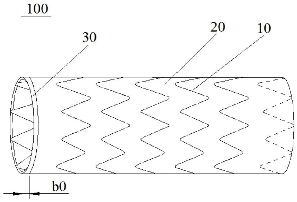
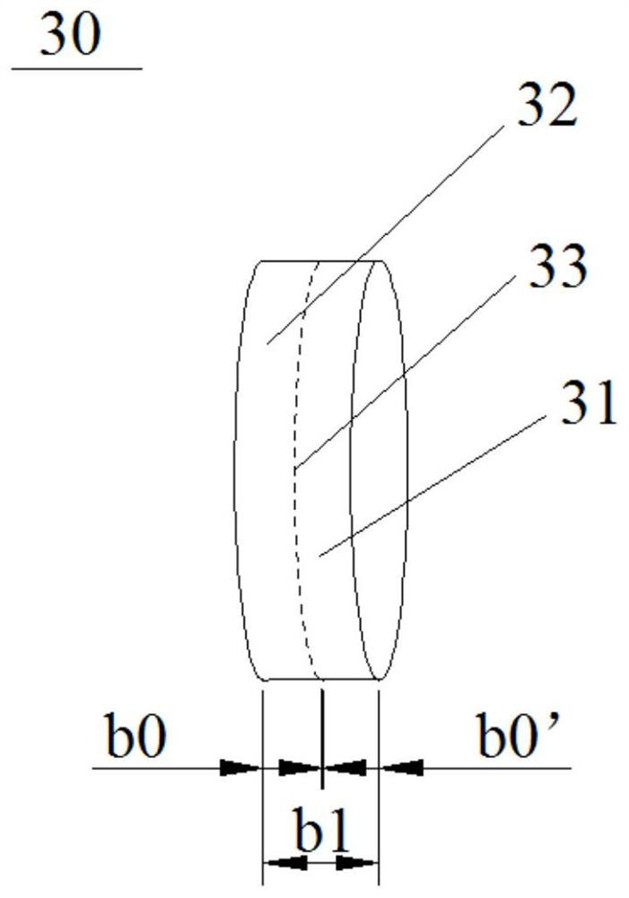
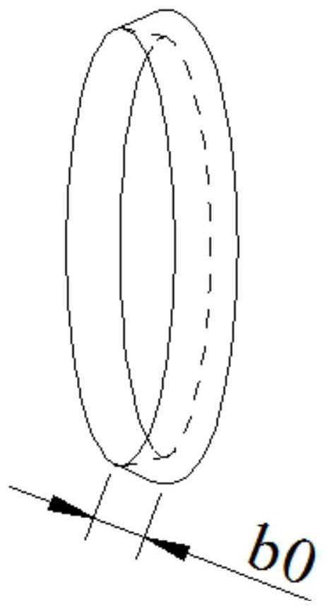
[0044] combine Figure 1 to Figure 3As shown, the stent graft 100 of this embodiment includes a plurality of wave coils 10 , a covering film 20 and a restraining member 30 . A plurality of wave coils 10 are arranged in the axial direction, thereby forming a skeleton for supporting the coating film 20 . The covering film 20 is disposed on the plurality of wave coils 10 , and the covering film 20 and the plurality of wave coils 10 form a hollow tubular structure with two open ends, at least one open edge of the hollow tubular structure is provided with a binding member 30 . The part is covered by the restraining member 30 , and the pore size of the restraining member 30 is smaller than the wire diameter of the coating film 20 . The wave ring 10 is a metal wave ring, which has better support and deformability. The coating 20 is woven from a wire, and the coating 20 of the present embodiment is a PET coating woven by yarn. The binding member 30 can be made of PET, PTFE or other...

Embodiment approach 2

[0053] combine Figure 4 to Figure 6 As shown, the stent graft 100 of this embodiment includes a plurality of wave coils 10 , a covering film 20 and a restraining member 30 . A plurality of wave coils 10 are arranged in the axial direction, thereby forming a skeleton for supporting the coating film 20 . The covering film 20 is disposed on the plurality of wave coils 10 , the covering film 20 and the plurality of wave coils 10 form a hollow tubular structure with openings at both ends, at least one open edge of the hollow tubular structure is provided with a binding member 30 , and the end of the covering film 20 is It is covered by the binding member 30 , and the pore size of the binding member 30 is smaller than the wire diameter of the coating film 20 . The restraint member 30 of the present embodiment includes a plurality of restraint units 40, the plurality of restraint units 40 are arranged at intervals at the opening of the at least one end of the hollow tubular structu...

Embodiment approach 3

[0062] combine Figure 9 and Figure 10 As shown, the stent graft 100 of this embodiment includes a plurality of wave coils 10 , a covering film 20 and a restraining member 30 . A plurality of wave coils 10 are arranged in the axial direction, thereby forming a skeleton for supporting the coating film 20 . The covering film 20 is disposed on the plurality of wave coils 10 , the covering film 20 and the plurality of wave coils 10 form a hollow tubular structure with openings at both ends, at least one open edge of the hollow tubular structure is provided with a binding member 30 , and the end of the covering film 20 is It is covered by the binding member 30 , and the pore size of the binding member 30 is smaller than the wire diameter of the coating film 20 .

[0063] According to the stent graft 100 of the present application, by arranging a strip 34 at the opening of at least one end of the hollow tubular structure formed by the membrane 20 and the plurality of wave coils 1...


PUM


Abstract

The invention discloses a covered stent which comprises a plurality of wave rings, and the wave rings are arranged in the axial direction. The covering film is arranged on the multiple wave rings, the covering film and the multiple wave rings form a hollow tubular structure with openings in the two ends, and the covering film is formed by weaving wires; the binding piece is arranged on the edge of an opening in at least one end of the hollow tubular structure, and the end of the covering film is wrapped by the binding piece, so that the wire at the end of the covering film is bound. According to the covered stent, the binding piece is arranged at the opening of at least one end of the hollow tube formed by the covering film and the multiple wave rings, the end of the covering film is wrapped by the binding piece, and therefore the wire at the end of the covering film is bound, and the cut edge wire of the covering film can be effectively prevented from stretching out of a hole of the binding piece; the situation that the blood vessel of the implanted part is stimulated and damaged by rough edge fibers on the edge of the covering film is avoided, and unnecessary damage to a patient is reduced.

Description

technical field [0001] The invention belongs to the technical field of medical equipment, and in particular relates to a covered stent. Background technique [0002] The covering material in the existing stent-graft is generally PTFE or PET. The PET film is usually woven by yarn. Due to the particularity of its structure, during the stent covering process, the PET film needs to be cut into the required length and shape, and then the stent corrugated coil and PET are covered. Membrane fixed connection. With the cut PET film, it is easy to produce burrs at the cut edge. After the stent with burrs is implanted into human blood vessels, it is easy to stimulate the human blood vessels to produce inflammation, resulting in the proliferation of inflammatory cells, which in turn reduces the lumen of the stent and affects the blood flow in the stent. In addition, the burr structure is unstable, and the yarn fibers are easily shed by the impact of blood flow. The shed yarn fibers w...

Claims


Application Information

Patent Timeline
IPC IPC(8): A61F2/07
CPCA61F2/07
Inventor 黄新鑫肖本好
Owner LIFETECH SCIENTIFIC (SHENZHEN) CO LTD
Why Eureka
Try Eureka