
Woodworking precise hammering auxiliary device and using method

An auxiliary device and precise technology, applied in distribution devices, packaging, manufacturing tools, etc., can solve problems affecting concrete forming, formwork deformation, personal safety, etc., and achieve convenient and fast operation and installation, shorten construction period, and improve construction quality and efficiency. Effect

Pending Publication Date: 2022-05-27
CHINA MCC17 GRP
View PDF8 Cites 0 Cited by
  • Summary
  • Abstract
  • Description
  • Claims
  • Application Information

AI Technical Summary

Problems solved by technology

A large part of carpentry needs to hammer nails to fix the formwork, but no matter how proficient the skilled workers are, they may miss the nails and hit the formwork during the hammering process, which may cause the formwork to deform and affect the concrete Forming, heavy will cause template damage or personal safety

Method used


Image

  • Woodworking precise hammering auxiliary device and using method
  • Woodworking precise hammering auxiliary device and using method

Examples


Embodiment 1

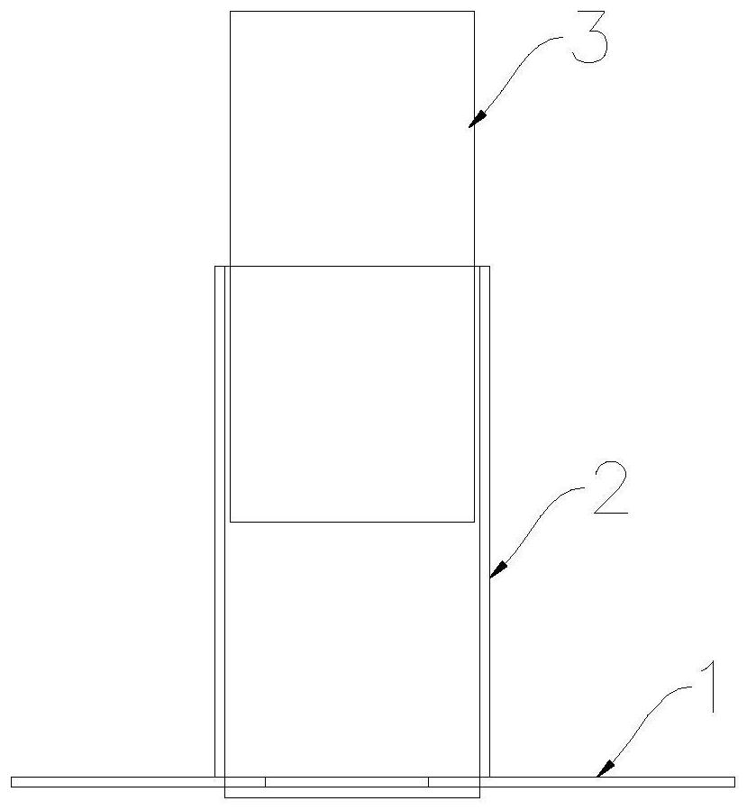
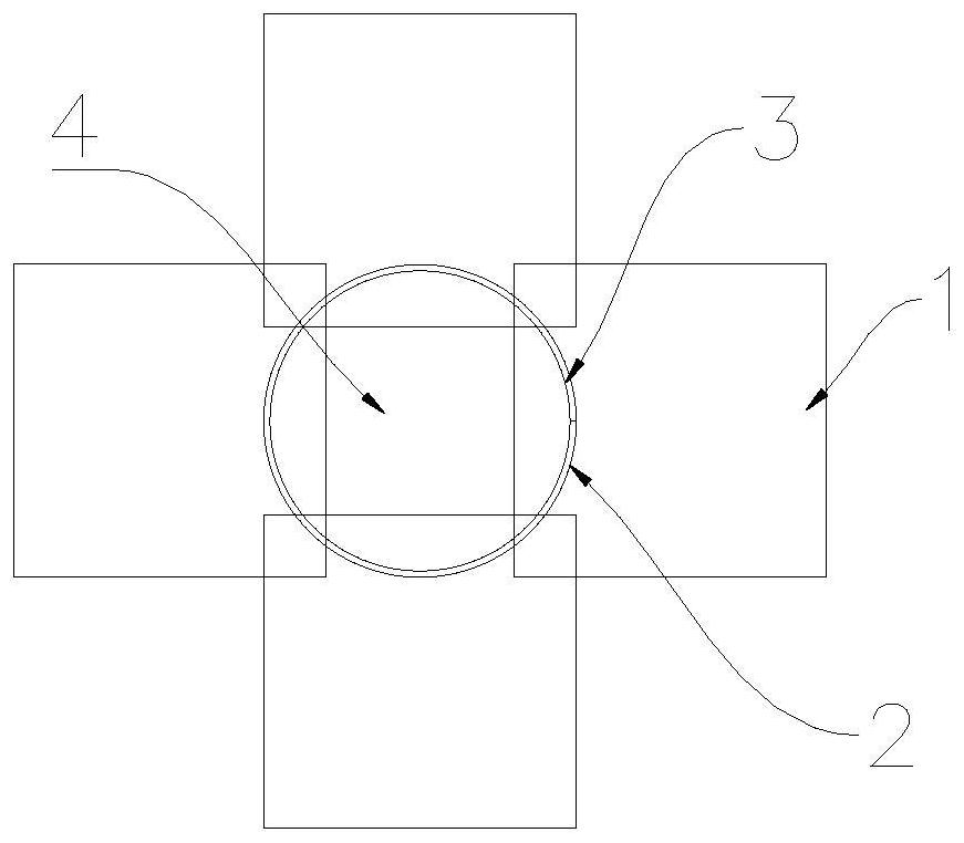
[0022] see figure 1 and figure 2 As shown, the present invention is a woodworking precision hammering auxiliary device, which includes a support plate 1, a guide tube 2 and an auxiliary hammer block 3, and a central through hole 4 is provided at the center of the support plate 1; the size of the guide tube 2 is larger than The size of the central through hole 4, the bottom of which is fixedly arranged on the support plate 1 outside the central through hole 4, and its central axis is on the same line as the center point of the central through hole 4; the auxiliary hammer block 3 and the guide tube 2 The inner side is adapted and the height is the same, and can be slidably arranged in the guiding circular tube 2 .

[0023] Preferably, the support plate 1 is formed by welding four square metal plates, the four metal plates are symmetrically arranged in four directions, and adjacent metal plates are overlapped at the corners and fixed by welding.

[0024] Preferably, the suppor...

Embodiment 2

[0034] The use method of a kind of woodworking precision hammering auxiliary device described in embodiment 1, the steps are as follows:

[0035] S1, take out the auxiliary hammer block 3 in the guide tube 2;

[0036] S2. Gently tap the nail on the template so that it can temporarily stand on the template without falling off, about 1cm can be nailed;

[0037] S3. Set the central through hole 4 of the support plate 1 and the guide tube 2 in the woodworking precision hammering auxiliary device to the nail, and move the nail to the center of the central through hole 4;

[0038] S4, put the auxiliary hammer block 3 into the guide tube 2;

[0039] S5. Use an ordinary hammer to strike from light to heavy until the auxiliary hammer block 3 is completely submerged into the guide tube 2. At this time, the four 50×50mm steel plates that form the support plate (1) are used to disperse the impact force, so that the template does not The effect of damage, but also to ensure the safety of...


PUM


Abstract

The invention discloses a woodworking precise hammering auxiliary device and a using method. The device comprises a supporting plate, a guiding round pipe and an auxiliary hammering block, and a center through hole is formed in the center of the supporting plate; the guide pipe is larger than the central through hole in size, the bottom of the guide pipe is fixedly arranged on the supporting plate on the outer side of the central through hole, and the central axis of the guide pipe and the central point of the central through hole are on the same straight line; and the auxiliary hammering block is matched with the inner side of the guide circular pipe, is as high as the guide circular pipe and is arranged in the guide circular pipe in a sliding manner. According to the woodworking precise hammering auxiliary device, the auxiliary device is low in manufacturing cost, simple in principle, free of site limitation and convenient and fast to operate and install, the woodworking operation can be effectively assisted in cooperation with the using method of the auxiliary device, and the construction quality and efficiency are improved.

Description

technical field [0001] The invention belongs to the field of building construction, and in particular relates to a woodworking precision hammering auxiliary device and a use method. Background technique [0002] A large part of the construction site is carpentry. A large part of the woodworking industry requires hammering nails to fix the formwork, but no matter how skilled the skilled worker is, they may hit the formwork without hitting the nail during the hammering process, which may cause the formwork to deform and affect the concrete. Forming, it will cause damage to the template or personal safety. Therefore, it is necessary to design a simple woodworking precision hammering auxiliary device to improve the installation quality and installation efficiency of the formwork, and to ensure the safety of construction workers. SUMMARY OF THE INVENTION [0003] Aiming at the problem of lack of corresponding auxiliary tools for woodworking hammering nails in the above-mentio...

Claims


Application Information

Patent Timeline
Patent Type & Authority Applications(China)
IPC IPC(8): B25C3/00
CPCB25C3/006
Inventor 黄宝林
Owner CHINA MCC17 GRP
Learn More