Eureka AIR delivers breakthrough ideas for toughest innovation challenges, trusted by R&D personnel around the world.

Injection mold with water blowing device

A technology for injection molds and injection tanks, which is applied in the directions of dry gas arrangement, cleaning methods and appliances, cleaning methods using tools, etc., can solve problems such as inconvenient water utilization, mold corrosion, and reduced service life of molds, so as to achieve improved effects and improved The service life of the mold and the effect of strong practicability

Pending Publication Date: 2022-05-27
东莞市邦德精密模具有限公司
View PDF0 Cites 0 Cited by
  • Summary
  • Abstract
  • Description
  • Claims
  • Application Information

AI Technical Summary

Problems solved by technology

[0004] Aiming at the deficiencies of the prior art, the present invention provides an injection mold with a water blowing device, which has the advantages of environmental protection, energy saving, and improved service life of the mold, and solves the problem of the existing injection molds in order to accelerate the molding speed in the mold cavity. After the mold is formed, it is usually necessary to cool the mold. At present, the commonly used cooling method is basically to cool the mold with water, but after cooling, it is not only inconvenient to use water, but also some water will remain in the mold. In the water channel, it is easy to cause the internal corrosion of the mold for a long time and reduce the service life of the mold

Method used


Image

  • Injection mold with water blowing device
  • Injection mold with water blowing device
  • Injection mold with water blowing device

Examples


Embodiment Construction

[0023] The technical solutions in the embodiments of the present invention will be clearly and completely described below with reference to the accompanying drawings in the embodiments of the present invention. Obviously, the described embodiments are only a part of the embodiments of the present invention, but not all of the embodiments. Based on the embodiments of the present invention, all other embodiments obtained by those of ordinary skill in the art without creative efforts shall fall within the protection scope of the present invention.

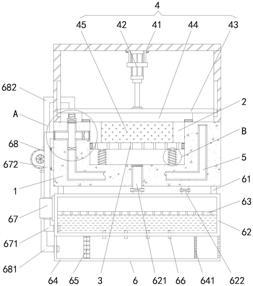
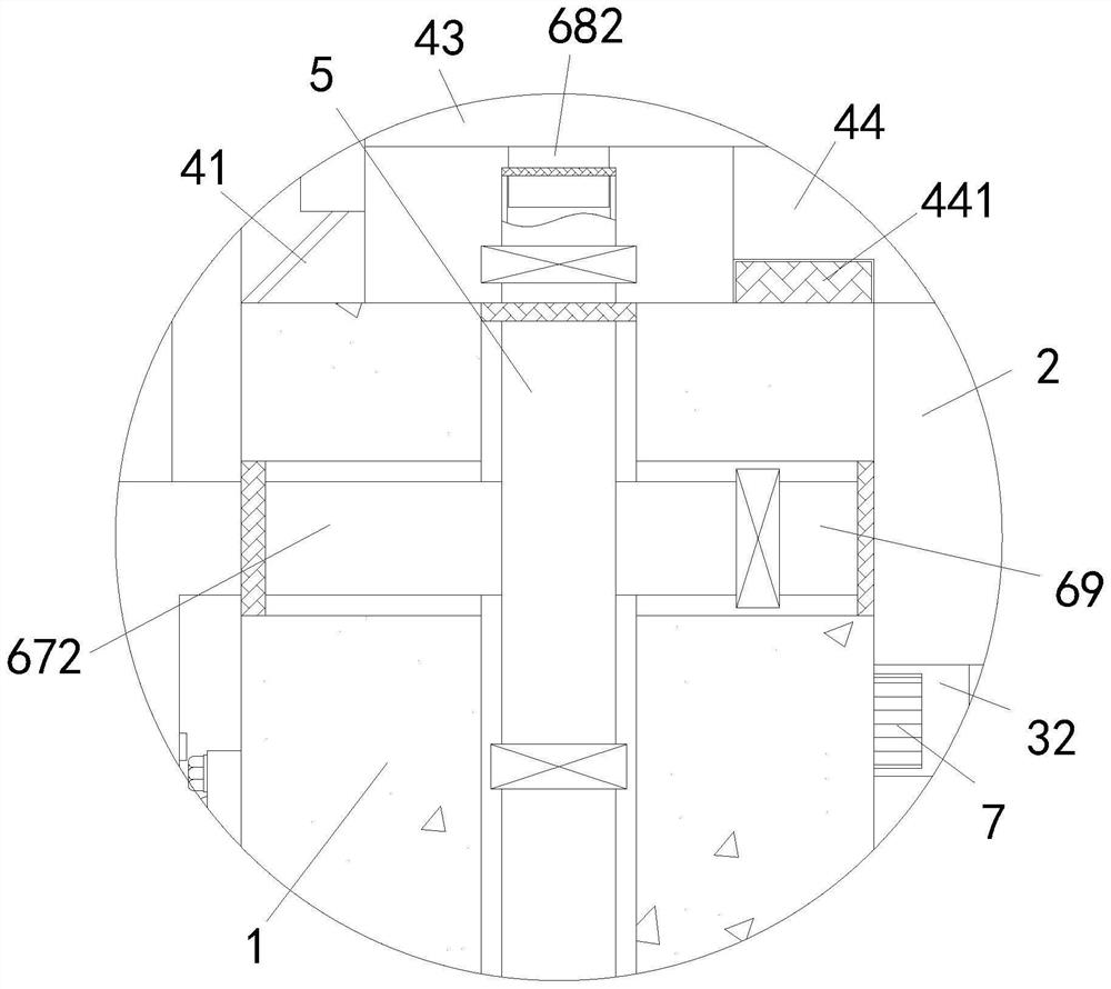
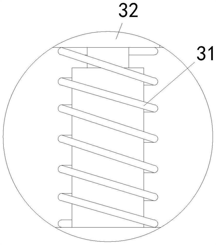
[0024] see Figure 1-3 , an injection mold with a water blowing device in this embodiment includes a lower mold seat 1, a lower mold seat 2 is opened on the top of the lower mold seat 1, a jacking assembly 3 is arranged inside the injection groove 2, and the lower mold The top of the base 1 is provided with a die assembly 4, the inside of the lower die base 1 is provided with a cooling pipe 5, the lower die base 1 is provided with a c...


PUM


Abstract

The injection mold with the water blowing device comprises a lower mold base, the top of the lower mold base is provided with a lower mold base body, a jacking assembly is arranged in an injection molding groove, the top of the lower mold base body is provided with a mold pressing assembly, a cooling pipe is arranged in the lower mold base body, and a regulation and control assembly is arranged on the lower mold base body. And a cleaning plate is arranged on the jacking assembly. According to the injection mold with the water blowing device, a hydraulic cylinder is started to drive an upper mold base to move up and down, so that a lifting plate is pressed to move up and down to drive a cleaning plate to move up and down to be attached to the interior of an injection molding groove for brushing and cleaning, and a fan is started to suck gas into a treatment box through ventilation holes; gas can be preheated when making contact with the heat collection plate layer, hot gas enters the exhaust pipe, enters the cooling pipe through the gas conveying pipe and enters the injection molding groove through the connecting pipe, and therefore the purpose of rapidly drying the cooling pipe and the injection molding groove is achieved, the water resource utilization effect is improved, and the service life of the mold is prolonged.

Description

technical field [0001] The invention relates to the technical field of injection moulds, in particular to an injection mould with a water blowing device. Background technique [0002] Injection mold is a tool for producing plastic products, and it is also a tool for imparting complete structure and precise dimensions to plastic products. Injection molding is a processing method used in mass production of certain parts with complex shapes. The injection molding machine injects high pressure into the mold cavity, and after cooling and solidifying, the molded product is obtained. [0003] In order to speed up the molding speed in the mold cavity of the existing injection mold, it is usually necessary to cool the mold after the mold is formed. The commonly used cooling method is basically to cool the mold with water. Water is used, and some water will remain in the water channel in the mold, which will easily corrode the inside of the mold for a long time and reduce the service...

Claims


Application Information

Patent Timeline
IPC IPC(8): B29C45/40B29C45/73B29C45/17B08B1/00F26B21/00
CPCB29C45/4005B29C45/73B29C45/1755F26B21/003B29C45/17B08B1/30Y02P70/10
Inventor 李邦
Owner 东莞市邦德精密模具有限公司
Why Eureka
Eureka Blog
Learn More