Laser collimator for 3D printer

A 3D printer and collimator technology, applied in 3D object support structures, mechanical equipment, manufacturing tools, etc., can solve the problems of lens deviation, time-consuming, vibration, etc., to avoid deviation, improve replacement rate, improve accuracy and effect of speed

Active Publication Date: 2022-05-27
NANJING CHAMLION LASER TECH CO LTD
View PDF8 Cites 0 Cited by
  • Summary
  • Abstract
  • Description
  • Claims
  • Application Information

AI Technical Summary

Problems solved by technology

[0004] The invention provides a laser collimator for 3D printers, the purpose of which is to solve the problem that the lenses in the existing laser collimator for 3D printers need to be aligned when they are put down. , it needs to be adjusted repeatedly to achieve the alignment of the lens, which takes a long time. At the same time, after the lens is put down, it needs to move back and forth to adjust the position of the lens. Vibration will occur during the adjustment process, which will easily cause the lens to be in the adjustment process. problem of deviation

Method used


Image

  • Laser collimator for 3D printer
  • Laser collimator for 3D printer
  • Laser collimator for 3D printer

Examples


Embodiment Construction

[0037] In order to make the purpose, technical solutions and advantages of the technical solutions of the present invention clearer, the following will clearly and completely describe the technical solutions of the embodiments of the present invention with reference to the accompanying drawings of the specific embodiments of the present invention. The same reference numbers in the figures represent the same parts. It should be noted that the described embodiments are part of the embodiments of the present invention, but not all of the embodiments. Based on the described embodiments of the present invention, all other embodiments obtained by those of ordinary skill in the art without creative work fall within the protection scope of the present invention.

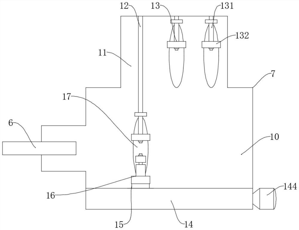
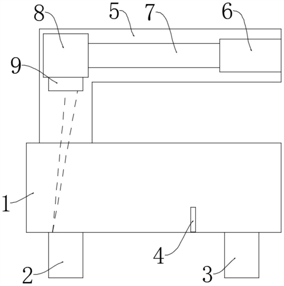
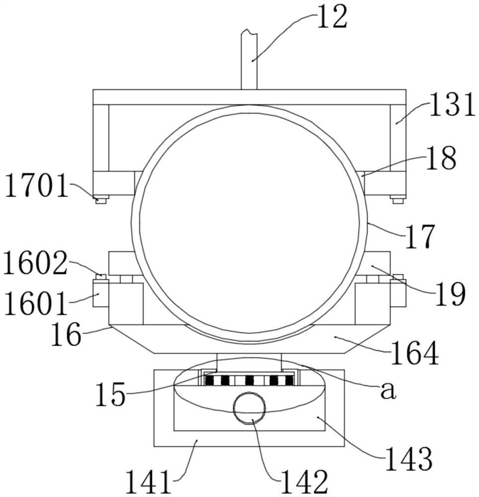
[0038] refer to Figure 1-6 , the embodiment of the present invention proposes a laser collimator for 3D printer, including a molding chamber 1, a molding cylinder 2 and a powder material cylinder 3 are arranged in the moldin...


PUM


Abstract

The invention provides a laser collimator for a 3D printer, and belongs to the technical field of equipment for the 3D printer, the laser collimator comprises a forming chamber, a forming cylinder and a powder cylinder are arranged in the forming chamber, a focusing field lens is arranged below a laser scanning galvanometer system, and a laser collimation assembly comprises a working chamber and a lens standby chamber. An upper fixing frame is installed at the output end of the telescopic rod, a buffering assembly is installed on the pushing assembly, a lower locking piece is installed on the buffering assembly, and an upper fixing block and a lower fixing block are arranged on the side edges of the upper end and the lower end of the lens. The laser collimator solves the problems that a lens in an existing laser collimator for the 3D printer needs to be aligned when being put down, alignment of the lens can be achieved only through repeated adjustment when alignment operation is conducted on the lens, time consumption is long, and meanwhile after the lens is put down, the lens needs to be moved back and forth to adjust the position of the lens, so that the alignment efficiency is high. And vibration is generated in the adjusting process, so that deviation is easily generated in the adjusting process of the lens.

Description

Technical field: [0001] The invention belongs to the technical field of equipment for 3D printers, and particularly relates to a laser collimator for 3D printers. Background technique: [0002] Ordinary printers used in daily life can print flat objects designed by computers, and the so-called 3D printers work basically the same as ordinary printers, but the printing materials are slightly different. The printing materials of ordinary printers are ink and paper, while 3D printers are equipped with metal , ceramics, plastics, sand and other different "printing materials" are real raw materials. After the printer is connected to the computer, the "printing materials" can be superimposed layer by layer through computer control, and finally the blueprint on the computer becomes real. In layman's terms, a 3D printer is a device that can "print" real 3D objects, such as printing a robot, printing a toy car, printing various models, and even food. The laser transmitter and the la...

Claims


Application Information

Patent Timeline
Patent Type & Authority Applications(China)
IPC IPC(8): B29C64/268B29C64/20B33Y30/00F16F15/067
CPCB29C64/268B29C64/20B33Y30/00F16F15/067Y02P10/25
Inventor 王林葛奕辉马桂殿
Owner NANJING CHAMLION LASER TECH CO LTD
Why Eureka
Try Eureka