A lateral stabilizer bar assembly and truck

A technology of stabilizer bar and stabilizer bar, which is applied to vehicle springs, vehicle components, and the upper structure of trucks, etc., which can solve problems such as low strength and easy breakage, poor ride comfort, and poor vibration damping effect of trucks, so as to improve anti-corrosion Rolling capability, improved comfort, improved integration effect

Active Publication Date: 2022-07-19
SINO TRUK JINAN POWER
View PDF2 Cites 0 Cited by
  • Summary
  • Abstract
  • Description
  • Claims
  • Application Information

AI Technical Summary

Problems solved by technology

[0002] The stabilizer bar assembly is an auxiliary elastic component in the truck suspension. Its function is to prevent the body from excessive lateral roll when turning. The stabilizer bar assembly is usually fixed on the lower arms of the left and right suspensions. When cornering, the centrifugal force will act on the rolling center of the car to cause the body to roll, causing the suspension of the inner wheel and the outer wheel to be stretched and compressed, resulting in the torsion of the stabilizer bar assembly. To suppress body roll, it will exert a downward force on the suspension of the curved outer wheel, and an upward force on the suspension of the curved inner wheel. The horizontal balance bar keeps the body at the same height as possible. It can be seen that the lateral stability The bar bears a large alternating load during operation; however, the stabilizer bar assembly in the prior art is a welded structure or a pressure riveting structure, which has low strength and is easy to break, has poor anti-rolling ability, and is not disassembled, which affects the stability of other components. Disassembly and maintenance space, often need to turn over the cab to achieve maintenance
[0003] On the other hand, the existing trucks have poor vibration damping effect and poor ride comfort

Method used


Image

  • A lateral stabilizer bar assembly and truck
  • A lateral stabilizer bar assembly and truck
  • A lateral stabilizer bar assembly and truck

Examples


Embodiment Construction

[0029] In order to make the objects, features and advantages of the present invention more obvious and understandable, the technical solutions in the present invention will be clearly and completely described below with reference to the accompanying drawings in the specific embodiments. Obviously, the implementation described below Examples are only some embodiments of the present invention, but not all embodiments. Based on the embodiments in this patent, all other embodiments obtained by persons of ordinary skill in the art without creative efforts shall fall within the scope of protection of this patent.

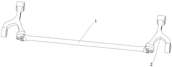
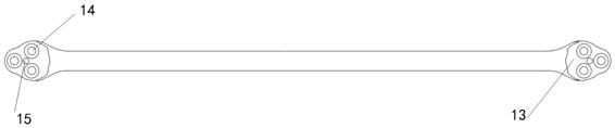
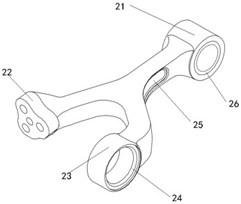
[0030] like Figure 1 to Figure 7 As shown, the present invention provides a stabilizer bar assembly, comprising a stabilizer bar 1 and a swing arm 2, the two ends of the stabilizer bar 1 are provided with mounting plates 13, and the mounting plate 13 is provided with three swing arm connecting screw holes 14 , the mounting plate 13 is also provided with a guide hole 15,...


PUM


Abstract

The invention provides a stabilizer bar assembly and a truck, and relates to the technical field of stabilizer bar assemblies. The swing arm has a Y-shaped structure, the trunk end of the swing arm is the cab connection part, the branch ends of the swing arm are the frame connection part and the stabilizer bar connection part respectively, the mounting plate and the stabilizer bar connection part Connected by high-strength bolts. The invention adopts the Y-shaped swing arm with high strength, balanced force, good anti-rolling ability, and can realize the detachable connection between the stabilizer bar and the swing arm, and only needs to disassemble the stabilizer bar to meet the requirements of the rear parts. Disassemble without flipping the cab.

Description

technical field [0001] The present invention relates to the technical field of a stabilizer bar, in particular to a stabilizer bar assembly and a truck. Background technique [0002] The stabilizer bar assembly is an auxiliary elastic element in the truck suspension. Its function is to prevent the body from excessive lateral roll when turning. The stabilizer bar assembly is usually fixed on the lower arms of the left and right suspensions. When cornering, centrifugal force will act on the rolling center of the car, causing the body to roll, causing the suspension of the inner wheel and outer wheel to stretch and compress, resulting in the torsion of the stabilizer bar assembly. Inhibit the body roll, it will exert a downward pressure on the suspension of the curved outer wheel, and exert an upward lifting force on the suspension of the curved inner wheel, the lateral balance bar makes the body as much as possible at the same height, visible and laterally stable The rod bear...

Claims


Application Information

Patent Timeline
Patent Type & Authority Patents(China)
IPC IPC(8): B60G21/055B62D33/06
CPCB60G21/0551B62D33/0604B60G2202/135
Inventor 曹东海高扬付东方崔志军雷保山李鑫李正鲁李正文
Owner SINO TRUK JINAN POWER
Why Eureka
Try Eureka