
River and lake bottom mud ecological desilting integrated equipment and ecological desilting system

A sediment and ecological technology, applied in construction, mechanically driven excavators/dredgers, earth movers/shovels, etc., can solve problems such as increased load on dredging vessels, reduce load and enhance dredging The effect of efficiency

Pending Publication Date: 2022-05-27
杭州市萧山区湘湖环境研究院
View PDF8 Cites 0 Cited by
  • Summary
  • Abstract
  • Description
  • Claims
  • Application Information

AI Technical Summary

Problems solved by technology

[0004] In order to make up for the deficiencies of the existing technology and solve the problem of increasing the load of the dredging ship caused by mixing a large amount of river water in the removed silt in the prior art, the present invention proposes an integrated equipment for ecological dredging of river and lake bottom mud and an ecological dredging system

Method used


Image

  • River and lake bottom mud ecological desilting integrated equipment and ecological desilting system
  • River and lake bottom mud ecological desilting integrated equipment and ecological desilting system
  • River and lake bottom mud ecological desilting integrated equipment and ecological desilting system

Examples


Embodiment 1

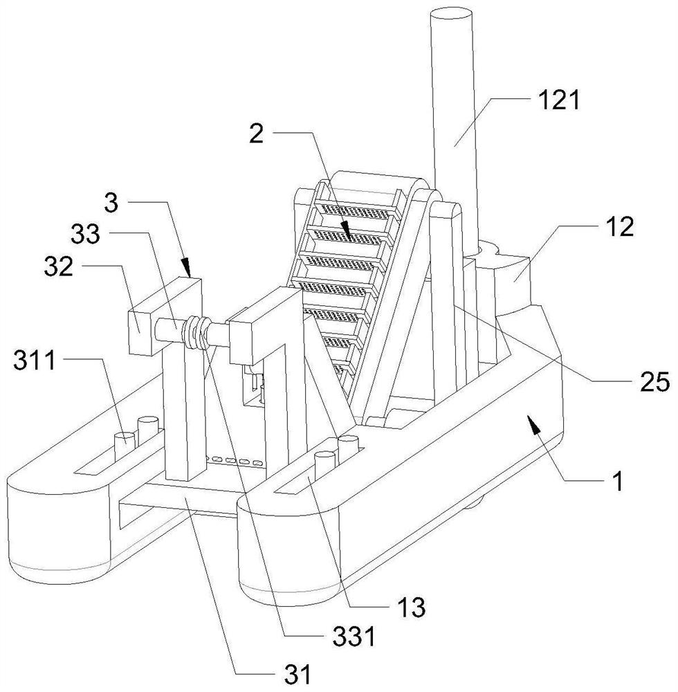
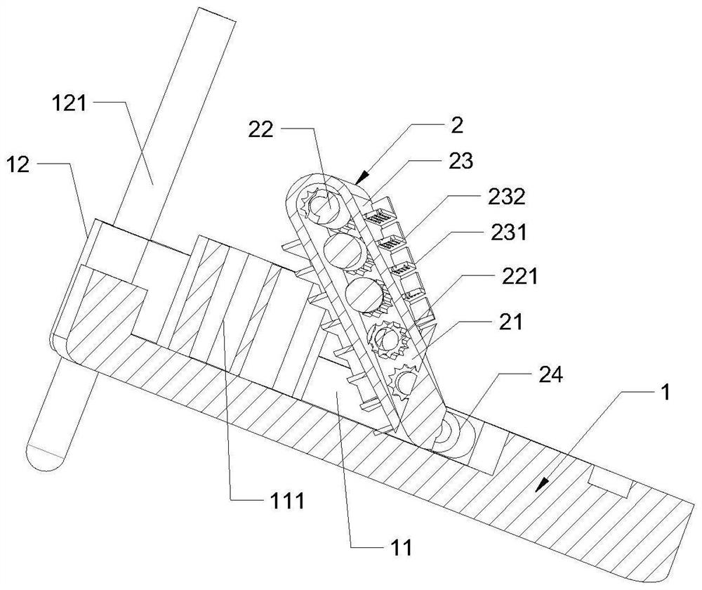
[0031] see Figure 1-Figure 5 , An integrated device for ecological dredging of river and lake bottom mud according to the present invention includes a dredging vessel body 1, and a support mechanism 3 is slidably connected to the upper end of the front end of the dredging vessel body 1; the dredging vessel body 1 The rear end is fixedly connected with a transmission mechanism 2; the transmission mechanism 2 is composed of a baffle 21, a rotating shaft 22, a conveyor belt 23 and a support column 25; the support column 25 is fixedly connected on both sides of the baffle 21; the rotating shaft 22 The conveyor belt 23 is rotatably connected to the rotating shaft 22 ; both sides of the rotating shaft 22 are fixedly connected with first gears 221 ; the first gears 221 are meshed and connected to On the inner wall of the conveyor belt 23; the two sides of the surface of the conveyor belt 23 are fixedly connected with bearing plates 231; the bearing plates 231 are fixedly connected w...

Embodiment approach

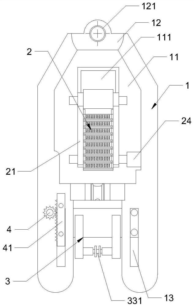
[0033] As an embodiment of the present invention, a limit plate 14 is fixedly connected to the middle surface of the dredging vessel body 1 ; a limit groove 141 is defined on the inner wall of the limit plate 14 ; the bottom surface of the limit plate 14 is A cylinder 142 is fixedly connected to the top; a support frame 15 is fixedly connected to the upper end of the cylinder 142 ;

[0034] When working, the support mechanism 3 is similar in structure to the traditional cutter suction dredger, and also has a reamer and a suction pipe arranged at the lower end of the reamer. The support frame 15 in the middle of the plate 14 can provide a certain support capacity for the suction pipe, and the cylinder 142 on the bottom surface of the limit plate 14 can drive the support frame 15 at the upper end to move up and down, so as to realize the adjustment of the angle of the outlet end of the suction pipe. , so that the angle between the point where the sludge falls and the inclined pl...

Embodiment 2

[0050] see Image 6 , Comparative Example 1, wherein another embodiment of the driving mechanism is that the driving mechanism is composed of a lead screw 42 and a ball nut 421; the lower end of the ball nut 421 is fixedly connected to the sliding rod 311; the ball nut 421 is rotatably connected to the lead screw 42.

[0051] During operation, the external third motor drives the lead screw 42 to rotate, and the lead screw 42 and the ball nut 421 fixedly connected to the sliding rod 311 rotate relative to the thread, so that the ball nut is driven by the third motor and the lead screw 42. 421 has the function of driving the bottom support mechanism 3 to move.

[0052] How it works: see Figure 1-Figure 5 , the structure of the dredging vessel body 1 is similar to that of the traditional cutter suction dredging vessel, wherein the front end of the dredging vessel body 1 is provided with a slidable support mechanism 3, and the supporting mechanism 3 can slide on the front end o...


PUM


Abstract

The invention belongs to the technical field of ecological desilting, and particularly relates to river and lake bottom mud ecological desilting integrated equipment which comprises a desilting ship body, and the upper side of the front end of the desilting ship body is slidably connected with a supporting mechanism; the rear end of the dredging ship body is fixedly connected with a transmission mechanism; the conveying mechanism is composed of a baffle, a rotating shaft, a conveying belt and a supporting column. Sludge at the bottom of a riverbed is sucked out through the conveying mechanism by utilizing the sludge suction pipeline and is discharged to the conveying mechanism through the other end of the pipeline, so that part of water flow discharged from the conveying mechanism can be discharged on a net plate on the conveying mechanism, and a large amount of water can be discharged in the process that the sludge reaches the top end of the conveying mechanism along with a conveying belt; the discharged water firstly exists in the groove, and the end, close to the limiting plate, of the groove is provided with a gradient, so that the water separated from the sludge is discharged into the river and lake again from the leaking holes, the load of the dredging ship body is reduced, and then the dredging efficiency of the dredging ship body is improved.

Description

technical field [0001] The invention belongs to the technical field of ecological dredging, in particular to an integrated equipment and ecological dredging system for river and lake bottom mud ecological dredging. Background technique [0002] The dredging of urban rivers and lakes is an important part of the urban water environment management in various cities to clear the water bodies. With the development of dredging technology, it is required to have environmental protection awareness while implementing the dredging of rivers and lakes, so as to realize environmental protection dredging and environmental protection dredging. . [0003] In the prior art, the dredging vessels used for dredging work in mature rivers and lakes are mainly cutter suction dredging vessels. When the cutter suction dredging vessel is working, the silt at the bottom of the river bed is driven to float by the stirring of the twisting head located at the front end of the hull. , so that it can be ...

Claims


Application Information

Patent Timeline
IPC IPC(8): E02F5/28E02F3/88E02F3/90E02F7/02E02F7/04E02F7/06
CPCE02F5/28E02F3/88E02F3/90E02F7/023E02F7/04E02F7/065E02F5/282E02F3/885E02F3/905
Inventor 张强王成童启明朱凯琳
Owner 杭州市萧山区湘湖环境研究院
Learn More