
Multifunctional agricultural power generation equipment for hydraulic engineering and power generation method of multifunctional agricultural power generation equipment

A technology for water conservancy projects and power generation equipment, applied in hydropower, mechanical equipment, engine components, etc., can solve problems such as lack of irrigation, waste of energy, and insufficient environmental protection, and achieve the effect of reducing irrigation costs and saving energy

Pending Publication Date: 2022-05-27
郭宁
View PDF0 Cites 0 Cited by
  • Summary
  • Abstract
  • Description
  • Claims
  • Application Information

AI Technical Summary

Problems solved by technology

[0004] Traditional hydroelectric power generation utilizes the potential energy in the water body, and farmland and rivers are usually inseparable. At present, to irrigate farmland with water from rivers, we can only rely on the fuel engine to drive the pump to draw water, and cannot use the flowing energy of river water to draw water. Irrigation is not efficient. Replaced by new energy, the cost of irrigation is high. Secondly, in the case of no potential energy in the water body, water energy cannot be converted into electrical energy to power agricultural equipment, which is a waste of energy and not environmentally friendly.

Method used


Image

  • Multifunctional agricultural power generation equipment for hydraulic engineering and power generation method of multifunctional agricultural power generation equipment
  • Multifunctional agricultural power generation equipment for hydraulic engineering and power generation method of multifunctional agricultural power generation equipment
  • Multifunctional agricultural power generation equipment for hydraulic engineering and power generation method of multifunctional agricultural power generation equipment

Examples


Embodiment 1

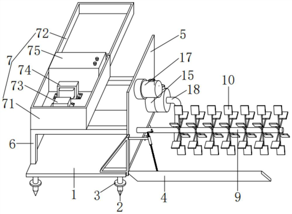
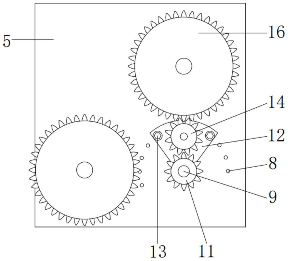
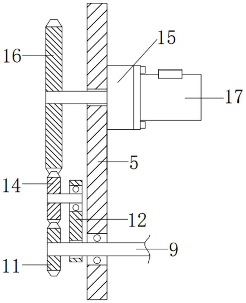
[0047] see Figure 1-3, In the embodiment of the present invention, a multi-functional agricultural power generation equipment for water conservancy projects includes a base 1, four support rods 2 and four backing plates 3, and the four support rods 2 are respectively fixedly connected to the four corners of the lower surface of the base 1, supporting The bottom of the rod 2 is a cone, which is convenient for it to be inserted into the ground. The backing plate 3 is fixedly connected to the middle of the outer wall of the supporting rod 2. The backing plate 3 can increase the contact area with the ground, and the base 1 is placed to sink. It also includes a water wave leveling mechanism 4. , vertical plate 5, reinforcing ribs 6, substation 7, positioning screw hole 8, first rotating shaft 9, water wheel 10, driving gear 11, rotating plate 12, positioning bolt 13, transmission gear 14, transmission 15, driven gear 16. The generator 17 and the water pumping mechanism 18, the wat...


PUM


Abstract

The invention relates to the field of hydraulic engineering, in particular to hydraulic engineering multifunctional agricultural power generation equipment which comprises a base, four supporting rods and four base plates, the four supporting rods are fixedly connected to the four corners of the lower surface of the base correspondingly, and the base plates are fixedly connected to the middles of the outer walls of the supporting rods. The base is fixedly connected to the right front end of the upper surface of the base; the vertical plate is fixedly connected to the right end of the upper surface of the base; one end of each reinforcing rib is fixedly connected to the front end and the rear end of the left side of the vertical plate, and the other end of each reinforcing rib is fixedly connected with the upper surface of the base; and the power transformation system is mounted on the upper surfaces of the reinforcing ribs. River water energy can be converted into electric energy to supply power to agricultural equipment, energy is saved, environment friendliness is achieved, farmland irrigation is achieved, irrigation is replaced by new energy, and the irrigation cost is reduced.

Description

technical field [0001] The invention relates to the technical field of water conservancy projects, in particular to a multi-functional agricultural power generation equipment for water conservancy projects and a power generation method thereof. Background technique [0002] Hydropower, a branch of water conservancy engineering, studies the science and technology of technical and economic issues such as engineering construction and production and operation of converting water energy into electrical energy. The water energy utilized by hydroelectric power generation is mainly the potential energy contained in the water body. In order to realize the conversion of water energy into electric energy, it is necessary to build different types of hydropower stations to replace coal-fired and oil-fired power generation, which has the advantages of environmental protection and energy saving; [0003] At present, the power generation method adopted is to use the water drop to drive the...

Claims


Application Information

Patent Timeline
Patent Type & Authority Applications(China)
IPC IPC(8): F03B13/06
CPCF03B13/06Y02E60/16
Inventor 郭宁宋飞向笛雨肖剑
Owner 郭宁
Learn More