
Vibration damping device with clutch

A technology of a vibration damping device and a clutch, applied in the field of vehicles, can solve the problems of increasing the axial size of the shock absorber and increasing the production cost, etc.

Pending Publication Date: 2022-05-27
SCHAEFFLER TECH AG & CO KG
View PDF2 Cites 0 Cited by
  • Summary
  • Abstract
  • Description
  • Claims
  • Application Information

AI Technical Summary

Problems solved by technology

This leads to a large increase in the axial dimension of the shock absorber after the clutch is integrated into the shock absorber, and increases the production cost

Method used


Image

  • Vibration damping device with clutch
  • Vibration damping device with clutch

Examples


Embodiment Construction

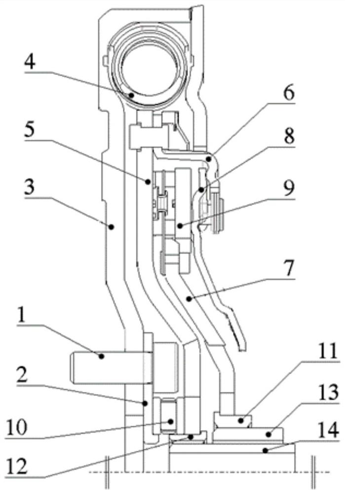
[0018] Specific embodiments of the vibration damping device according to the present invention will be described below with reference to the accompanying drawings. The following detailed description and accompanying drawings are used to illustrate the principles of the present invention by way of example, the present invention is not limited to the described preferred embodiments, and the protection scope of the present invention is defined by the claims.

[0019] According to an embodiment of the present invention, there is provided a damping device with a clutch, in other words, the damping device integrates the functions of the damper with the clutch. Such damping devices are used in the drive trains of various motor vehicles, and are especially suitable for hybrid vehicles.

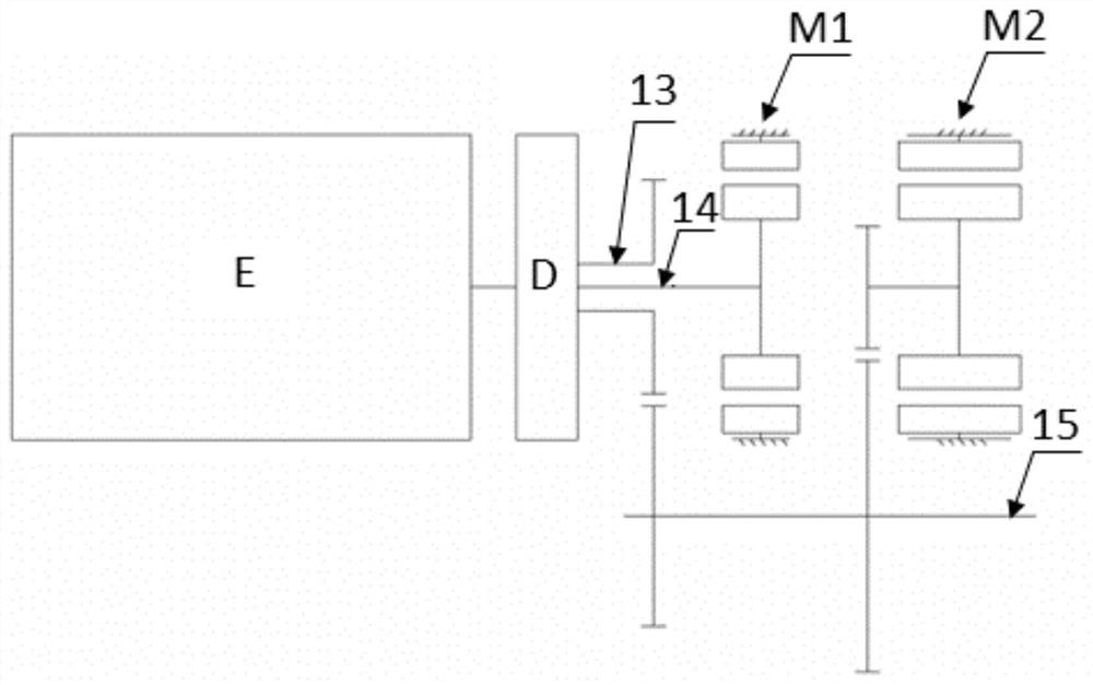
[0020] figure 1 The layout of the drive train to which the damping device D according to the embodiment of the invention is applied is schematically shown. like figure 1 As shown, the hybrid vehicl...


PUM


Abstract

The invention relates to a damping device with a clutch. The vibration damping device includes: a flywheel; a damper output flange disposed coaxially with the flywheel; and the damper spring is abutted between the flywheel and the damper output flange along the rotation direction of the damper device, so that torque can be transmitted between the flywheel and the damper output flange. The damping device further comprises a clutch disc, the clutch disc and the damper output flange are coaxially arranged, the clutch disc is located on the side, opposite to the flywheel, of the damper output flange in the axial direction, and the clutch disc can abut against the damper output flange in the axial direction so that torque can be transmitted between the damper output flange and the clutch disc. Or the clutch disc is separated from the damper output flange to disconnect torque transmission between the damper output flange and the clutch disc. Wherein the damper output flange and the clutch disc can form two parallel torque transmission ports of the damping device. The damping device is compact in layout.

Description

technical field [0001] The present invention relates to the technical field of vehicles. In particular, the present invention relates to a vibration damping device having a clutch. Background technique [0002] In today's society with increasingly serious environmental and energy problems, new energy vehicles have received more and more attention from the industry. Among the current various new energy vehicles, a hybrid vehicle that uses an internal combustion engine and an electric motor to drive together is a common type. Hybrid vehicle layouts can often be divided based on where the electric machines are located in the driveline. For example, P1 refers to the layout where the motor is placed after the engine and before the clutch, while P3 refers to the layout where the motor is placed at the output of the transmission. For a vehicle with a P1 motor, especially a hybrid vehicle with a P1+P3 layout, in order to reduce the layout size of the drive train, it is often incl...

Claims


Application Information

Patent Timeline
IPC IPC(8): F16F15/30F16F15/133F16D13/70F16D13/58
CPCF16F15/30F16F15/133F16D13/70F16D13/585F16D13/58Y02T10/62
Inventor 肖荣亭陈广露
Owner SCHAEFFLER TECH AG & CO KG
Learn More