
Testing equipment and method for testing FCW, AEBS and RCWS

A testing method and equipment technology, which is applied in vehicle testing, machine/structural component testing, measuring devices, etc., can solve the problem of inability to accurately control the cooperative motion state of the tested vehicle and the target vehicle, inaccurate test indicators, and test influences. Major problems, to achieve the effect of improving test consistency and test accuracy, precise speed control, and reducing longitudinal speed control errors

Pending Publication Date: 2022-05-27
RES INST OF HIGHWAY MINIST OF TRANSPORT
View PDF0 Cites 0 Cited by
  • Summary
  • Abstract
  • Description
  • Claims
  • Application Information

AI Technical Summary

Problems solved by technology

[0006] The present invention provides a test equipment and method for testing FCW, AEBS and RCWS, one purpose of which is to have the function of reducing the lateral deviation and longitudinal deviation, and solve the problem that the lateral deviation and longitudinal deviation have great influence on the test; Another purpose is to solve the inaccurate and difficult-to-control problems of important test indicators such as the distance between two vehicles and vehicle speed during the test, so as to achieve the effect of dynamic and precise control of indicators such as vehicle distance and vehicle speed for users; the last one The purpose of the project is to solve the problem that the current test methods cannot accurately control the coordinated motion state of the vehicle under test and the target vehicle, resulting in the inability to test the condition that the distance between the vehicle in front of FCW or AEBS is too close

Method used


Image

  • Testing equipment and method for testing FCW, AEBS and RCWS
  • Testing equipment and method for testing FCW, AEBS and RCWS
  • Testing equipment and method for testing FCW, AEBS and RCWS

Examples


Embodiment 1

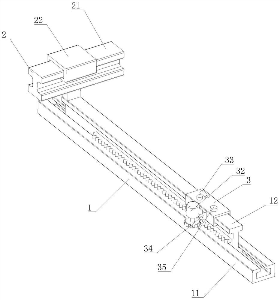
[0043] First, as Figure 1-6 As shown, the present invention provides a test equipment for testing FCW, AEBS and RCWS, comprising a guide rail-1, the guide rail-1 includes a fixed rail-11 and a moving rail 12, and the moving rail 12 is slidably connected to the fixed rail-11. On the top, the top of the moving rail 12 is provided with a guide rail 2 , the guide rail two 2 includes a fixed rail two 21, the fixed rail two 21 is fixedly installed on the top of the moving rail 12, and the top of the fixed rail two 21 is slidably connected with a moving slider 22, which moves A rack is fixedly installed on the front of the rail 12, a collision target base 3 is installed on the top of the moving rail 12, a motion motor 32 is fixedly installed on the front of the collision target base 3, and an output shaft of the motion motor 32 is fixedly installed with a gear, and the back of the gear is fixed with the gear. The front of the rack is engaged, and the motion motor 32 , the gear and t...

Embodiment 2

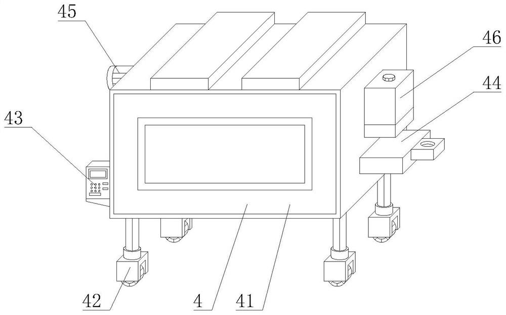
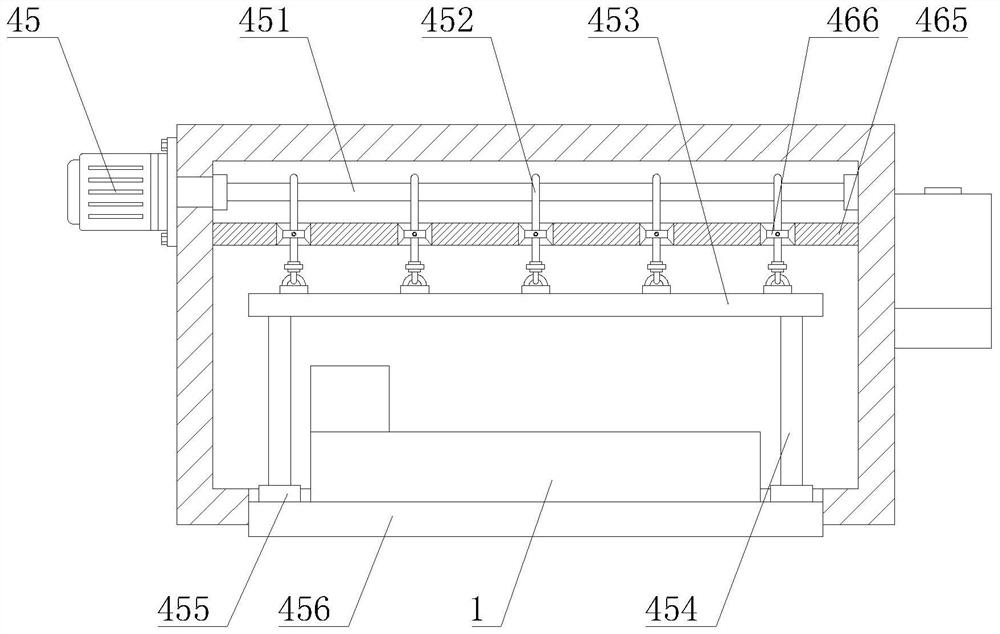
[0045] like Figure 1-6 As shown, on the basis of Embodiment 1, the present invention provides a technical solution: preferably, a universal moving wheel rod 42 is fixedly installed on the bottom of the storage and protection box 41, and a left side of the storage and protection box 41 is fixedly installed with a The console 43, the right side of the storage and protection box 41 is fixedly welded with a traction plate 44, the right side of the storage and protection box 41 is fixedly installed with a lubricating tank 46, and the outer wall of the connecting ring seat 455 is fixedly installed with a fixed cylinder 4541. The fixed cylinder The inner cavity of 4541 is slidably connected with a sliding insert block 4543, and the end of the sliding insert block 4543 away from the connecting rod 454 is fixedly connected with an elastic piece 4542. An extension frame 461 is fixedly installed at the bottom of 46, a pump 462 is fixedly installed in the inner cavity of the extension fr...

Embodiment 3

[0047] Second, as Figure 1-6 As shown, the present invention provides a test method for testing FCW, AEBS and RCWS, and the test method for testing FCW, AEBS and RCWS includes the following methods:

[0048] Method 1. Forward collision low-speed moving vehicle warning / automatic emergency braking condition test;

[0049] Method 2. Forward collision with the front of the vehicle is too small for early warning / automatic emergency braking;

[0050] Method 3. Forward collision test under the condition of early warning / automatic emergency braking when the vehicle under test is stationary;

[0051] Method 4: Rear Collision Warning Test.


PUM


Abstract

The invention discloses testing equipment and method for testing FCW, AEBS and RCWS, and relates to the technical field of vehicle performance testing, the testing equipment comprises a first guide rail, and the first guide rail comprises a first fixed rail and a moving rail. The road motion of the target vehicle in the test is converted into the track motion, the transverse motion of the target vehicle is eliminated, the transverse deviation is reduced by 50%, the two objects originally moving respectively in the test are converted into the relative motion, meanwhile, the longitudinal deviation is reduced by 50%, the test accuracy is greatly improved, and the test efficiency is improved. FCW / AEBS testing consistency and testing accuracy are improved, and the problem that conventional testing equipment and methods cannot test the working conditions of early warning / emergency braking of too small time headway of FCW and AEBS is solved; meanwhile, the speed and distance of relative movement can be accurately controlled through the system, and the problems that in current testing, the relative distance and respective speed of the tested vehicle and the target vehicle are difficult to control, the accuracy is low, the number of effective testing times is small, and the testing efficiency is low are solved.

Description

technical field [0001] The invention relates to the technical field of vehicle performance testing, in particular to a testing equipment and method for testing FCW, AEBS and RCWS. Background technique [0002] Forward Collision Warning System (FCW) is a system that automatically detects target vehicles or obstacles through sensors such as radar and cameras, detects potential forward collision hazards, and sends out warning signals to remind drivers to reduce collision risks. The core indicators of the test are Early Warning Distance to Collision Time (TTC) (TTC refers to the time required for the vehicle under test to collide with the target obstacle at time t); Vehicle Automatic Emergency Braking System (AEBS) automatically detects the target vehicle or vehicle through sensors such as radar and camera. Obstacles, detect potential danger of forward collision, send out warning signals to remind the driver, and activate the braking system of the vehicle to avoid or mitigate co...

Claims


Application Information

Patent Timeline
IPC IPC(8): G01M17/007
CPCG01M17/0078
Inventor 高金周炜李文亮
Owner RES INST OF HIGHWAY MINIST OF TRANSPORT
Learn More