Optical detection device with protection mechanism

A technology of optical detection and protection mechanism, which is used in measurement devices, material analysis by optical means, scientific instruments, etc., can solve the problems of reducing the progress of circuit board detection, reducing practicability, increasing maintenance costs, etc., and achieves convenient cleaning, scanning and detection. , The effect of reducing production quality and prolonging service life

Pending Publication Date: 2022-05-27
张增
View PDF0 Cites 3 Cited by
  • Summary
  • Abstract
  • Description
  • Claims
  • Application Information

AI Technical Summary

Problems solved by technology

[0005] The purpose of the present invention is to provide an optical detection device with a protection mechanism to solve the problem that the existing optical detection device proposed in the background art has poor protection and is prone to accidental impact during use, resulting in damage to the device and affecting The normal use of optical detectors increases maintenance costs and reduces the inspection progress of circuit boards, and most of the existing optical detectors do not have the function of lifting and adjusting, so they cannot adjust the height according to the application environment, which affects the production process. The clear detection of the circuit board may ignore some problems of the circuit board, which reduces the production quality of the circuit board, and the existing optical detector is easy to accumulate dust on the surface of the display during long-term use, which affects the staff's understanding of the circuit. For the judgment of problems on the board, the method of regular cleaning increases the workload of the staff and reduces the practical problems in actual use

Method used


Image

  • Optical detection device with protection mechanism
  • Optical detection device with protection mechanism
  • Optical detection device with protection mechanism

Examples


Embodiment Construction

[0026] The technical solutions in the embodiments of the present invention will be clearly and completely described below with reference to the accompanying drawings in the embodiments of the present invention. Obviously, the described embodiments are only a part of the embodiments of the present invention, rather than all the embodiments. Based on the embodiments of the present invention, all other embodiments obtained by those of ordinary skill in the art without creative efforts shall fall within the protection scope of the present invention.

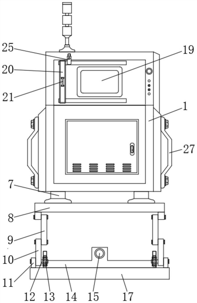
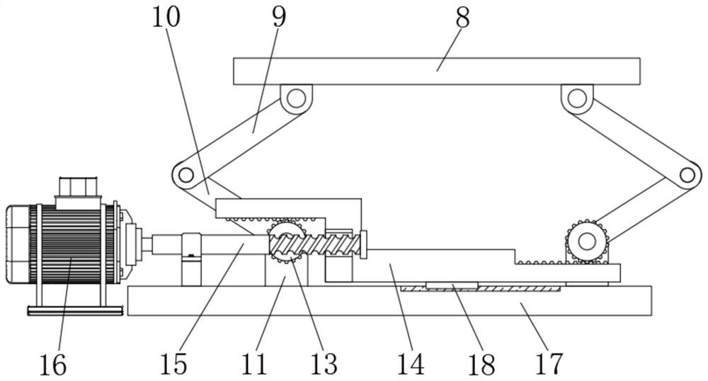
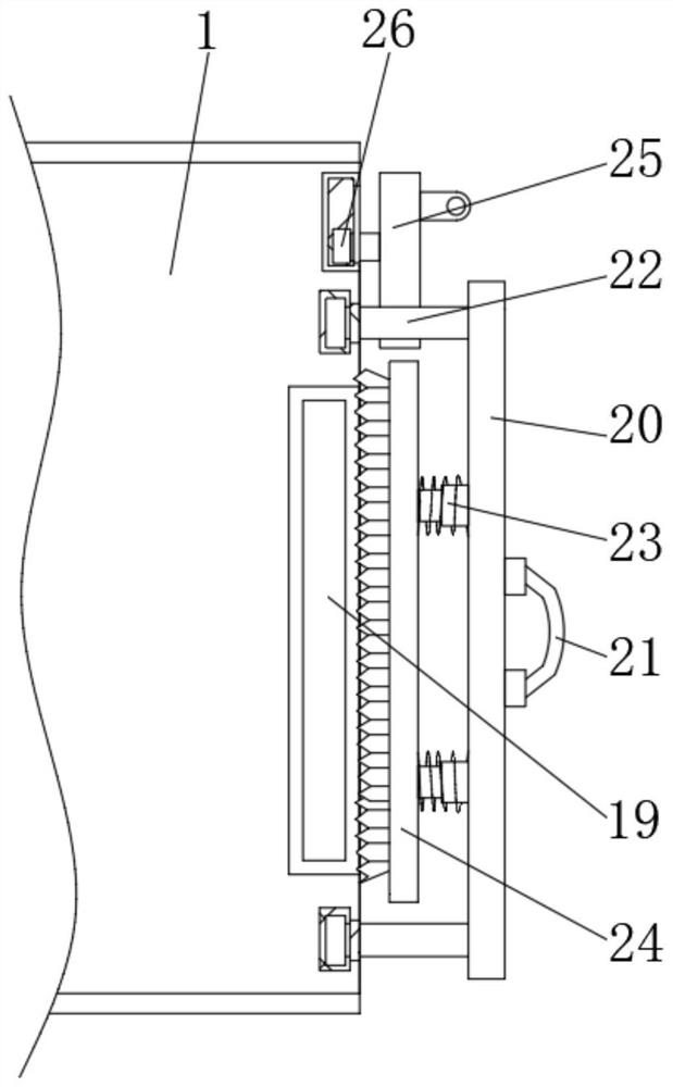
[0027] see Figure 1-4 , an embodiment provided by the present invention: an optical detection device with a protective mechanism, comprising an optical detector 1 and a drive motor 16, a slot 2 opened on the bottom surface of the optical detector 1, and the inner wall of the top of the slot 2 A fixed frame 3 is fixedly connected, and a shock-absorbing spring 4 is welded on the top inner wall of the fixed frame 3, and a moving block ...


PUM


Abstract

The invention relates to the technical field of optical detection devices, in particular to an optical detection device with a protection mechanism, which comprises an optical detector and a driving motor, a slotted hole is formed in the surface of the bottom end of the optical detector, a fixed frame is fixedly connected to the inner wall of the top end of the slotted hole, and a damping spring is welded to the inner wall of the top end of the fixed frame; moving blocks are welded to the sides, away from the inner wall of the top end of the fixing frame, of the damping springs. According to the optical detector, the damping springs are arranged, under the elastic action of the damping springs, vibration generated when the optical detector works can be reduced, meanwhile, downward pressure borne by the optical detector can be reduced, and the service life of the optical detector is prolonged; the anti-collision strength of the surface of the optical detector can be improved, the surface of the optical detector is protected, and the situation that normal use is affected due to the fact that the optical detector is accidentally impacted and damaged is avoided.

Description

technical field [0001] The invention relates to the technical field of optical detection devices, in particular to an optical detection device with a protective mechanism. Background technique [0002] Optical detector is a new type of testing technology that has emerged in recent years, but it has developed rapidly. Many manufacturers have launched optical detector testing equipment. During automatic testing, the machine automatically scans the circuit board through the camera, collects images, and tests the soldering. The point is compared with the qualified parameters in the database, and after image processing, the defects on the circuit board are checked, and the defects are displayed and marked through the display or automatic signs for maintenance personnel to repair. [0003] Existing optical detectors have poor protection, and are prone to accidental impact during use, resulting in damage to the device, affecting the normal use of the optical detector, increasing ma...

Claims


Application Information

Patent Timeline
Patent Type & Authority Applications(China)
IPC IPC(8): G01N21/956G01N21/01
CPCG01N21/95607G01N21/01G01N2021/95615G01N2021/95646G01N2021/0112
Inventor 张增
Owner 张增
Why Eureka
Try Eureka