Calculation method of exposed steel column rigid connection column foot

A calculation method and exposed technology, applied in design optimization/simulation, architecture, instruments, etc., can solve problems such as unreliability, inaccurate calculation results, large bending stress, etc., achieve high accuracy and reliability, and economical calculation results effect of rationality

Active Publication Date: 2022-05-27
HUBEI IND CONSTR GRP
View PDF3 Cites 0 Cited by
  • Summary
  • Abstract
  • Description
  • Claims
  • Application Information

AI Technical Summary

Problems solved by technology

[0004] However, the existing algorithm has the following defects: 1. The base plate of the column base will deform under the load at the lower end of the steel column. With the increase of the load, the base plate of the column base will change from elastic deformation to plastic deformation, and finally plastic failure will occur, resulting in the failure of the steel structure , that is, in actual use, the base plate of the column foot will be plastically damaged under the load of the lower end of the steel column. It will cause the calculated bending stress to be too large, so that the thickness of the calculated column base plate will be too large. In actual material selection, due to the limited thickness specifications of the steel plate, a specification larger than the calculated thickness will be selected, because this calculation method is conservative, resulting in The cost of the steel plate is high and the economy is poor; 2. The stress state of the rigidly connected column foot of the steel column under the joint action of axial force and bending moment is related to the eccentric state. When it is in a small eccentric state, axial pressure will be generated on the pressure side , there will be no axial tension at the anchor bolts on the tension side, the axial pressure on the compression side is resisted by the pressure on the bottom plate of the column foot, and the tension side does not need anchor bolts to resist the axial tension, when it is large eccentricity state, axial pressure will be generated on the compression side, and axial tension will be generated at the anchor bolts on the tension side. The anchor bolts are resisted by tension, but the existing algorithm does not consider these two eccentric states separately, resulting in inaccurate and unreliable calculation results

Method used


Image

  • Calculation method of exposed steel column rigid connection column foot
  • Calculation method of exposed steel column rigid connection column foot
  • Calculation method of exposed steel column rigid connection column foot

Examples


Embodiment Construction

[0042] In order to make the purposes, technical solutions and advantages of the embodiments of the present invention clearer, the technical solutions in the embodiments of the present invention will be clearly and completely described below with reference to the accompanying drawings in the embodiments of the present invention. Obviously, the described embodiments These are some embodiments of the present invention, but not all embodiments. It should be understood that the specific embodiments described herein are only used to explain the present invention, but not to limit the present invention. Based on the embodiments of the present invention, all other embodiments obtained by those of ordinary skill in the art without creative work fall within the protection scope of the present invention.

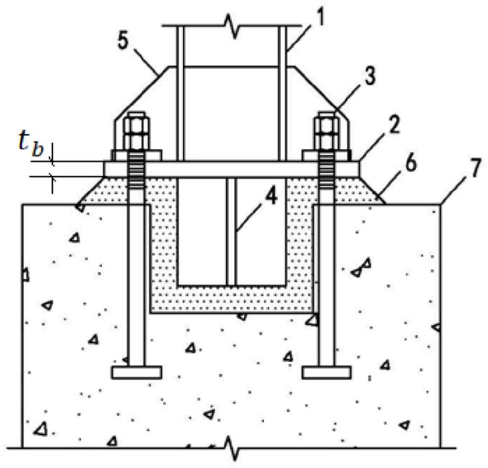
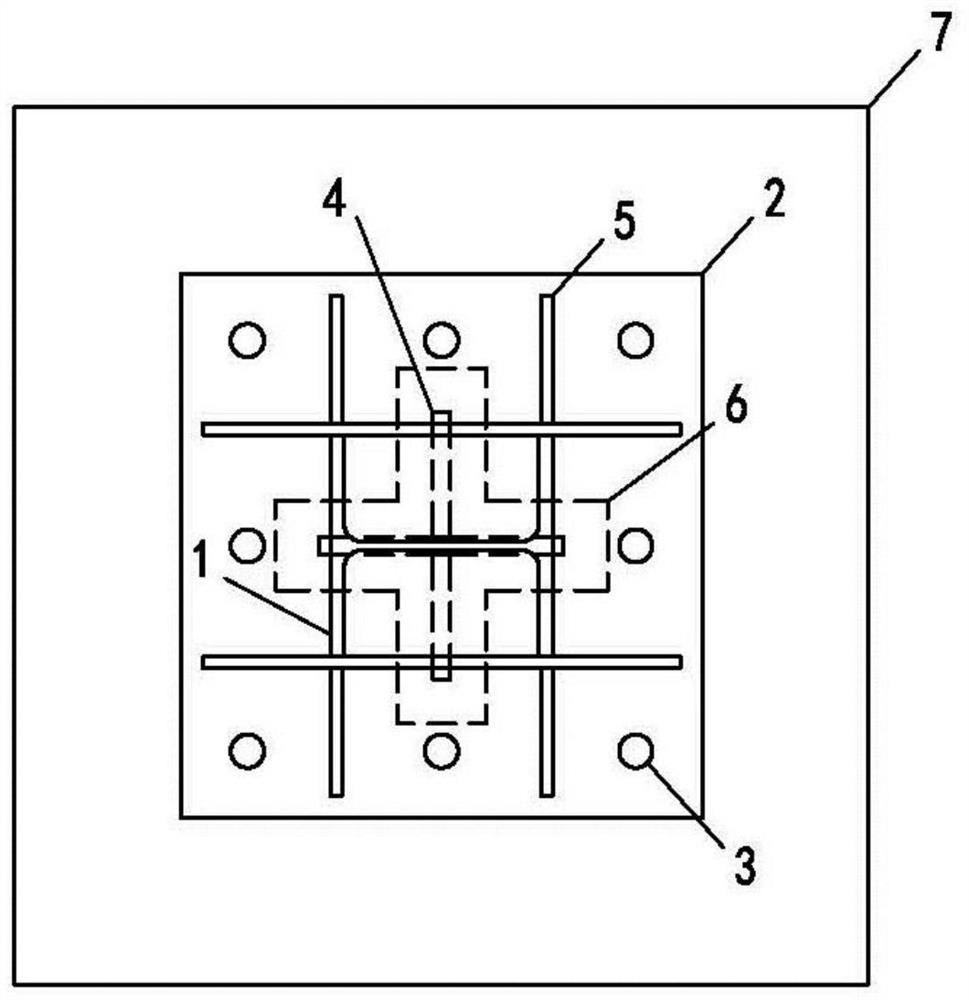
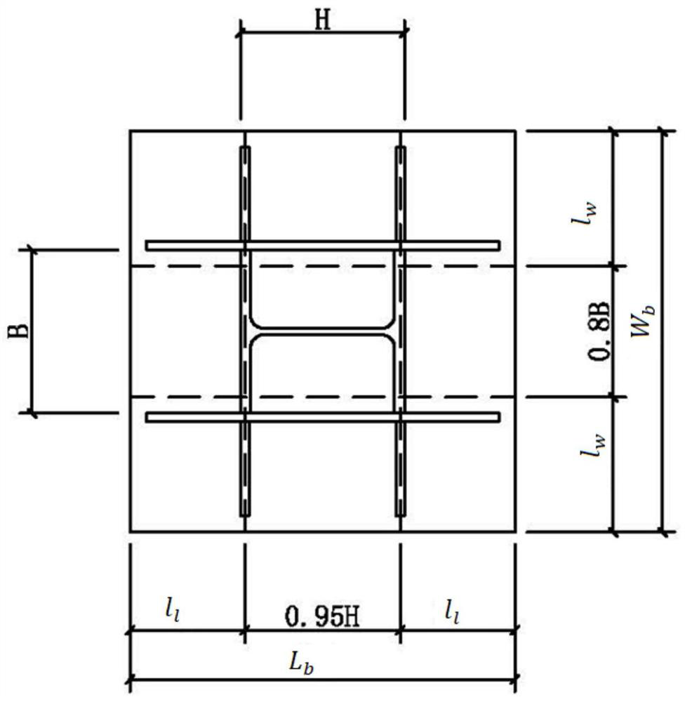
[0043] Combine below Figure 1-Figure 6 Describe the calculation method of the exposed steel column rigidly connected to the column foot of the present invention.

[0044] The steel ...


PUM


Abstract

The invention belongs to the technical field of steel structure design, and provides a calculation method of an exposed steel column rigid connection column foot, the steel column rigid connection column foot comprises a steel column, a column foot bottom plate, a stiffening rib and a concrete foundation, the calculation method of the column foot bottom plate comprises the following steps: if the steel column rigid connection column foot is in a small eccentric state, the calculation thickness tb of the column foot bottom plate is equal to max (tb pressure, 25mm), and the calculation thickness tb of the column foot bottom plate is equal to max (tb pressure, 25mm); a tb pressure calculation method is limited; and if the steel column rigid connection column foot is in a large eccentric state, tb = max (tb pressure, tb pull, 25mm), and a calculation method of tb pressure and tb pull is limited. According to the method, the bending stress of the column base bottom plate is calculated based on the plastic section modulus, meanwhile, calculation is conducted according to different eccentric states of the steel column rigid connection column base and combined with the stress state of the steel column rigid connection column base, and the economic rationality, accuracy and reliability of the calculation result can be improved.

Description

technical field [0001] The invention belongs to the technical field of steel structure design, and particularly relates to a calculation method for an exposed steel column rigidly connected to a column foot. Background technique [0002] The steel column just connected to the column foot is an important node in the steel structure, such as figure 1 , figure 2 As shown, the exposed steel column rigidly connected column foot generally includes steel column 1, column foot bottom plate 2, anchor bolt 3, shear key 4, stiffener 5, grouting material 6 and concrete foundation 7. When installing, pour concrete first. Foundation 7. At the same time, 4 anchor bolts 3 are pre-buried in the concrete foundation, and shear grooves are reserved in the foundation. At the bottom of the steel column 1, the stiffening ribs 5 are welded between the two sides of the steel column 1 and the bottom plate 2 of the column foot. The concrete foundation 6 is fixedly connected, and the grouting mater...

Claims


Application Information

Patent Timeline
Patent Type & Authority Applications(China)
IPC IPC(8): G06F30/13G06F30/20E04B1/24G06F119/02G06F119/14
CPCG06F30/13G06F30/20E04B1/24G06F2119/02G06F2119/14E04B2001/2463
Inventor 俞栋华侯国发吴金池陈翠姣李振兴马屹梅浩
Owner HUBEI IND CONSTR GRP
Why Eureka
Try Eureka