
Photoelectric detection array anode and multi-anode photomultiplier

A photoelectric detection and anode technology, applied in the field of photoelectric detection, can solve the problems of loss of fast time characteristics, slow time information, high cost, and achieve the effect of saving electronics

Pending Publication Date: 2022-05-27
INST OF HIGH ENERGY PHYSICS CHINESE ACADEMY OF SCI
View PDF0 Cites 0 Cited by
  • Summary
  • Abstract
  • Description
  • Claims
  • Application Information

AI Technical Summary

Problems solved by technology

However, there is a risk in such a test, that is, once fan-in and fan-out processing is performed on a fast signal of tens of picoseconds (ps), its time information will immediately become very slow, and the fast time characteristic carried by the original signal will be lost, that is, Very fast fan-in and fan-out electronics are difficult to obtain or develop, and the cost is high

Method used


Image

  • Photoelectric detection array anode and multi-anode photomultiplier
  • Photoelectric detection array anode and multi-anode photomultiplier
  • Photoelectric detection array anode and multi-anode photomultiplier

Examples


Embodiment Construction

[0027] Example embodiments will now be described more fully with reference to the accompanying drawings. Example embodiments, however, can be embodied in various forms and should not be construed as limited to the examples set forth herein; rather, these embodiments are provided so that this disclosure will be thorough and complete, and will fully convey the concept of example embodiments to those skilled in the art. The drawings are merely schematic illustrations of the present disclosure and are not necessarily drawn to scale. The same reference numerals in the drawings denote the same or similar parts, and thus their repeated descriptions will be omitted.

[0028] Furthermore, the described features, structures, or characteristics may be combined in any suitable manner in one or more embodiments. In the following description, numerous specific details are provided in order to give a thorough understanding of the embodiments of the present disclosure. However, those skill...


PUM


Abstract

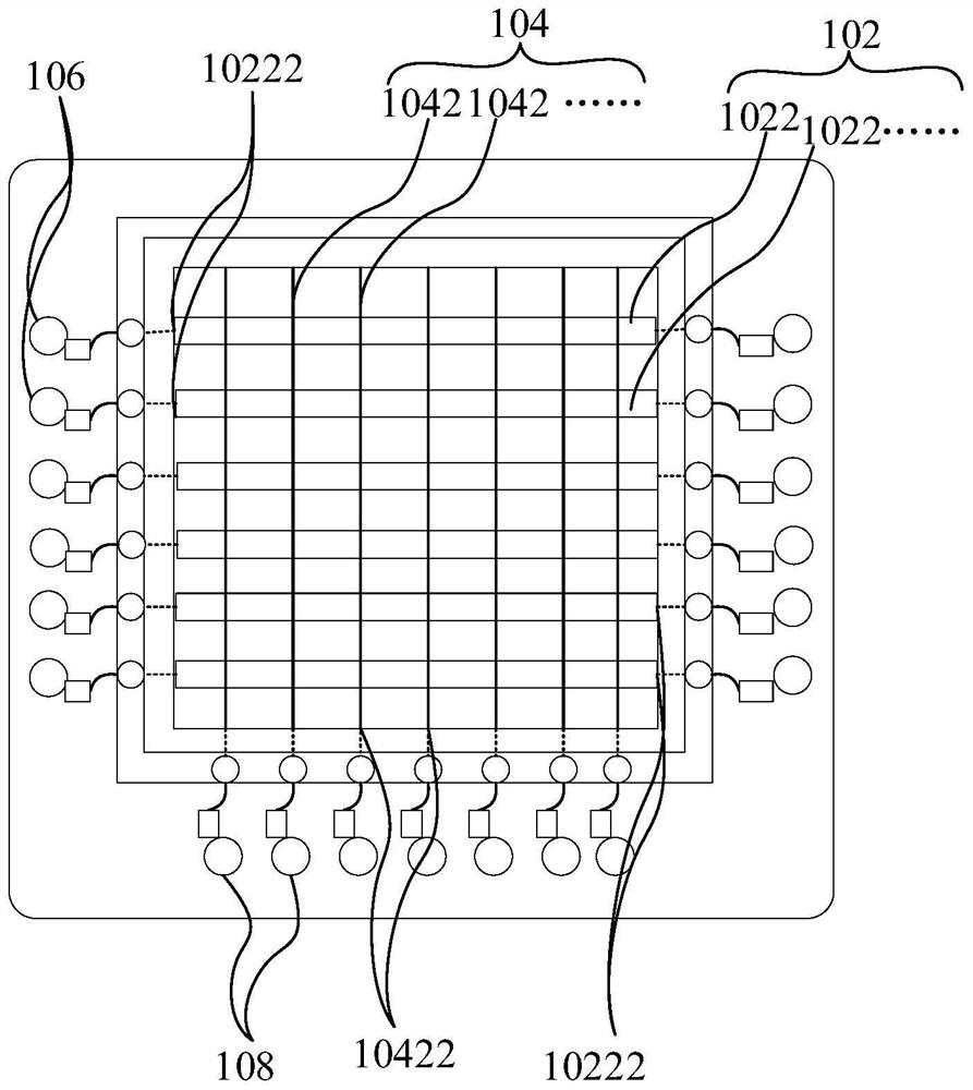
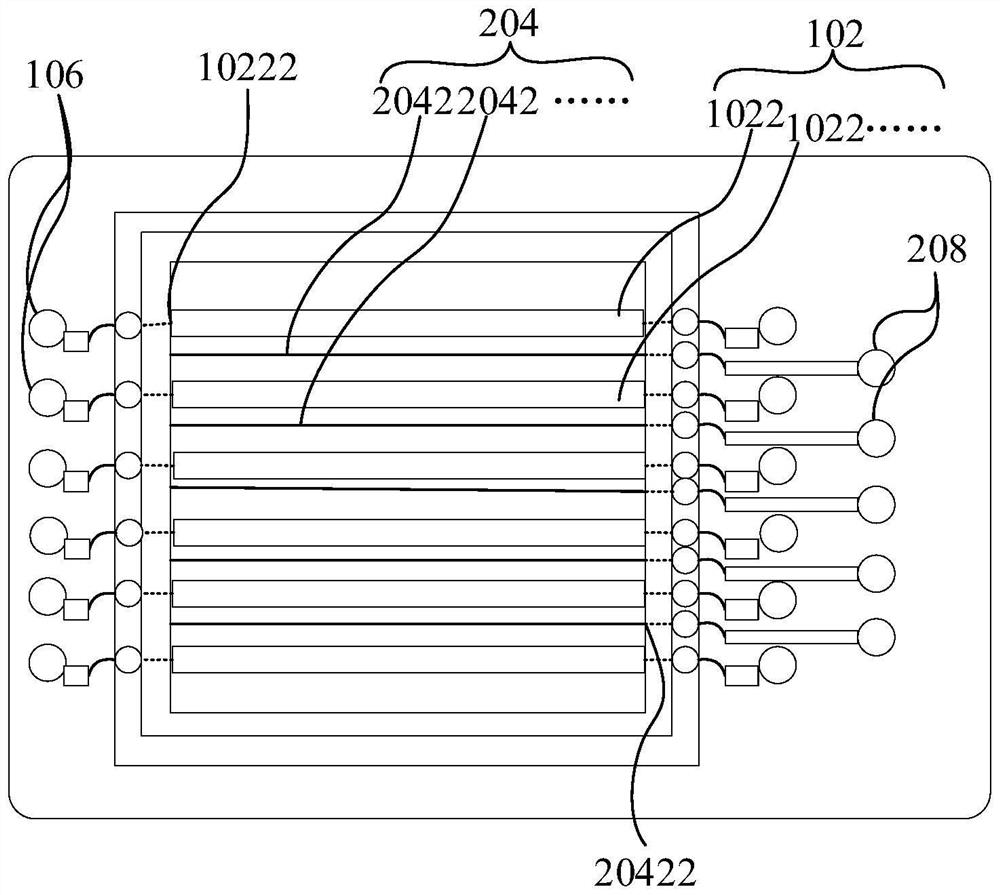
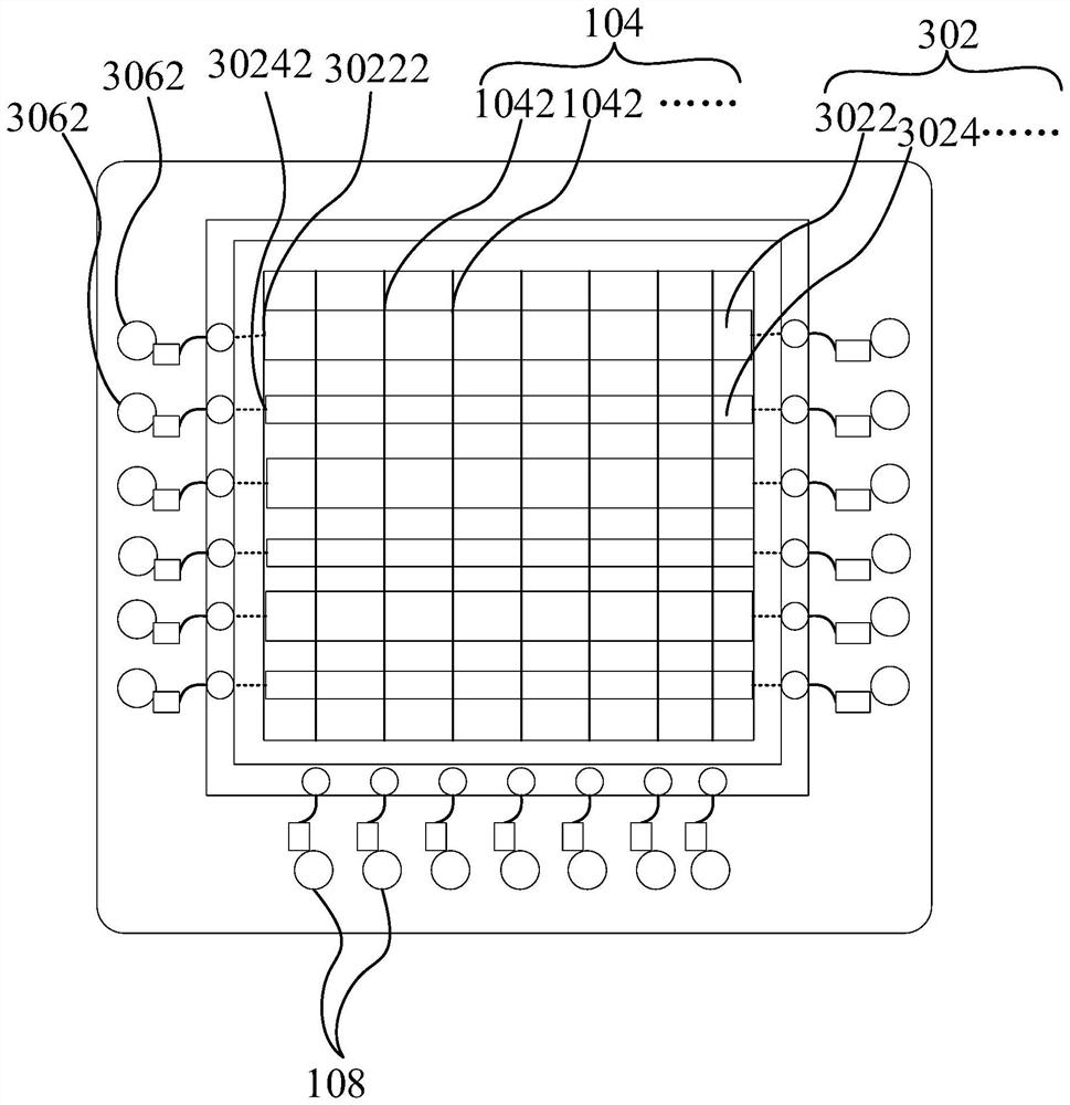
The invention provides a photoelectric detection anode and a multi-anode photomultiplier, and relates to the technical field of photoelectric detection. The photoelectric detection anode comprises a position detection layer and a time detection layer, the position detection layer comprises a plurality of metal strips, the plurality of metal strips are arranged in parallel, and the end part of each metal strip in the plurality of metal strips is connected with a first signal reading device which is used for acquiring position information through acquired charges; the time detection layer comprises a plurality of metal wires which are arranged in parallel, and the end part of each metal wire in the plurality of metal wires is connected with a second signal reading device which is used for acquiring time information through the waveform of the acquired signal. According to the invention, the position information of the photomultiplier position detection layer and the time information of the time detection layer can be read independently at the same time.

Description

technical field [0001] The present disclosure relates to the technical field of photodetection, in particular, to a photodetection array anode and a multi-anode photomultiplier tube. Background technique [0002] A photomultiplier tube is a vacuum detection device that converts extremely weak optical signals into electrical signals. Micro-Channel Plate Photo-Multiplier Tube (MCP-PMT) refers to a photomultiplier tube with a micro-channel plate as an electron multiplier system, compared with the traditional electrostatic focusing dynode structure photomultiplier tube. , First of all, the moving distance of electrons from the photocathode to the anode is greatly shortened in structure, and the electron multiplication characteristics of the microchannel plate determine that the photomultiplier tube of this structure has many specific properties, especially it can achieve high Accurate location-resolved and time-resolved. [0003] In the related art, the data readout of the pho...

Claims


Application Information

Patent Timeline
Patent Type & Authority Applications(China)
IPC IPC(8): H01J43/12H01J43/04H01J43/24
CPCH01J43/246H01J43/12H01J43/045Y02P70/50
Inventor 钱森马丽双朱瑶
Owner INST OF HIGH ENERGY PHYSICS CHINESE ACADEMY OF SCI
Learn More