[0046] Example
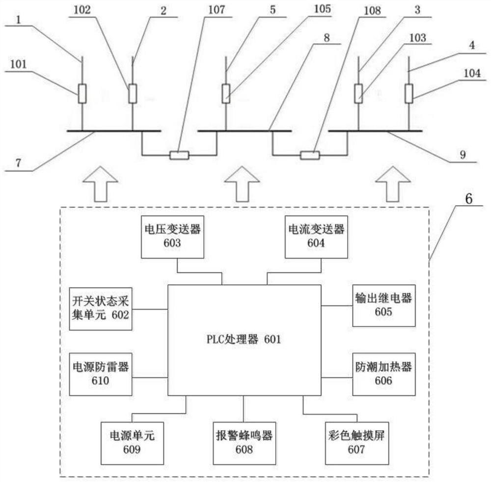
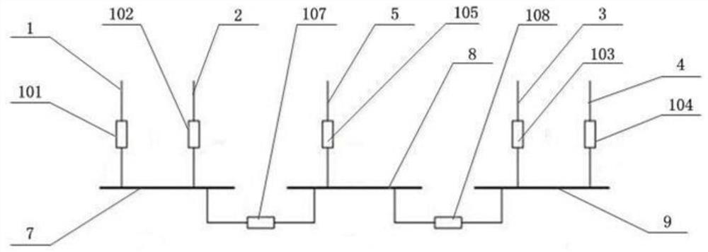
[0047] like Figure 1 to Figure 2 As shown, this embodiment provides a PLC-based high-voltage side standby power supply automatic switching device, including PLC6, first bus 7, second bus 8, third bus 9, first in-plant power supply line 1, second In-plant power supply line 2, third in-plant power supply line 3, fourth in-plant power supply line 4, fifth external power supply line 5, first incoming line switch 101, second incoming line switch 102, third incoming line Line switch 103, fourth incoming line switch 104, fifth incoming line switch 105, first bus tie switch 107, second bus tie switch 108, wherein PLC is a programmable logic controller, a For the digital operation controller of automatic control, the control instructions can be loaded into the memory for storage and execution at any time. PLC is the acronym of the English Programmable Logic Controller. PLC is widely used in various working conditions and is widely used. As the core of automatic switching control, PLC has stably controlled the automatic switching device and realized the automatic switching function of various operation modes.
[0048] In this embodiment, the first in-plant power supply line, the second in-plant power supply line, the third in-plant power supply line, the fourth in-plant power supply line, and the fifth external power supply line pass through the first The incoming line switch, the second incoming line switch, the third incoming line switch, the fourth incoming line switch and the fifth incoming line switch constitute the incoming line self-casting, the first bus bar, the second bus bar and the third bus bar pass through the first bus tie switch , The second bus tie switch constitutes the automatic switching of the bus, and the automatic switching in various operation modes is realized by PLC centralized detection and centralized control. A variety of suitable operation modes are formed. Among the three busbars, two of them are powered by the in-plant power supply, and one is powered by the external power supply.
[0049] In this embodiment, the PLC includes a PLC processor 601, a switch state acquisition unit 602, a voltage transmitter 603, a current transmitter 604, an output relay 605, a color touch screen 607, and an alarm buzzer all connected to the PLC processor. 608, power supply unit 609, power lightning arrester 610, the entire PLC structure is simple, the switch state acquisition unit, voltage transmitter, current transmitter realize the detection function, the output relay realizes the self-switching execution function, and the color touch screen is set , realizes a visual human-machine interface interface, which is convenient to display the real-time operating status and the setting of device parameters. The power supply unit provides a stable power supply to the PLC. In addition, by setting the alarm buzzer on the PLC, it can be effective in the process of automatic switching. The user is reminded that the stable operation of the PLC is ensured by setting the power lightning protection device on the PLC. The entire automatic switching device not only realizes the automatic switching function, but also the connection line is very simple. At the same time, in this embodiment, the PLC processor adopts Schneider M580 controller product, and a moisture-proof heater 606 is provided on the PLC, which ensures the stable operation of the PLC and further enhances the stability of the entire automatic switching device. In this embodiment , Moisture-proof heater, power lightning arrester, alarm buzzer are connected with the PLC processor.
[0050] like Figure 3 to Figure 10 As shown, this embodiment also provides a PLC-based automatic switching method of a high-voltage side standby power supply automatic switching device, including the following steps:
[0051] S1: According to the incoming line auto-switching logic between the first in-plant power supply line, the second in-plant power supply line, the third in-plant power supply line, the fourth in-plant power supply line, and the fifth external power supply line, And the segmented self-switching logic between the first bus, the second bus, and the third bus, divide the self-switching logic into nine operating modes, and preset them in the PLC, set the closing and blocking conditions according to the self-switching logic, and pre-set Set in PLC;
[0052] S2: Collect the first busbar, the second busbar, the third busbar, the first in-plant power supply line, the second in-plant power supply line, the third in-plant power supply line, the fourth in-plant power supply line, 5. The voltage and current information of the incoming line of external power supply, and the first incoming line switch, the second incoming line switch, the third incoming line switch, the fourth incoming line switch, the fifth incoming line switch and the first bus tie switch are collected by PLC , the switch state quantity of the second bus tie switch, judge the current operating state and use the current operating state as the starting condition for automatic switching;
[0053] S3: According to the judged operating state and starting conditions, under the control of the PLC, the first incoming switch, the second incoming switch, the third incoming switch, the fourth incoming switch, the fifth incoming switch, the One bus tie switch and the second bus tie switch make corresponding tripping or closing self-throwing actions,
[0054] S4: According to the closing and blocking conditions, the first incoming switch, the second incoming switch, the third incoming switch, the fourth incoming switch, the fifth incoming switch, the first bus tie switch, and the second bus tie switch are respectively Perform closing and blocking.
[0055] In this embodiment, according to the incoming line automatic switching logic and the bus automatic switching logic, the automatic switching logic is divided into nine operating modes, and the closing and blocking conditions are set according to the automatic switching logic, and the information is collected through the PLC to determine the current operating state and Taking the current operating state as the starting condition for automatic switching, according to the judged running state and starting conditions, the automatic switching device makes corresponding tripping or closing automatic switching actions, and according to the closing and blocking conditions, each incoming switch and The bus tie switch is closed and locked separately. The whole automatic switching method not only realizes the automatic switching of various operation modes, but also has high stability under the centralized control of the PLC.
[0056] In this embodiment, in step S1, the nine operating modes are:
[0057] Method 1: The first incoming switch and the third incoming switch are in position, the second incoming switch, the fourth incoming switch and the fifth incoming switch are in the separate positions, and the first bus tie switch and the second bus tie switch have and only one is in the quantile;
[0058] Method 2: The first incoming line switch and the fourth incoming line switch are in position, the second incoming line switch, the third incoming line switch and the fifth incoming line switch are in the separate position, and the first bus tie switch and the second bus tie switch have and only one is in the quantile;
[0059] Mode 3: The second incoming switch and the third incoming switch are in position, the first incoming switch, the fourth incoming switch and the fifth incoming switch are in the separate positions, and the first bus tie switch and the second bus tie switch have and only one is in the quantile;
[0060] Method 4: The second incoming line switch and the fourth incoming line switch are in position; and only one is in the quantile;
[0061] Mode 5: The first incoming switch, the first bus tie switch, and the second bus tie switch are in position, and the second incoming switch, the third incoming switch, the fourth incoming switch, and the fifth incoming switch are in position;
[0062] Mode 6: The second incoming switch, the first bus tie switch, and the second bus tie switch are in position, and the first incoming switch, the third incoming switch, the fourth incoming switch, and the fifth incoming switch are in position;
[0063] Method 7: The third incoming switch, the first bus tie switch, and the second bus tie switch are in position, and the first incoming switch, the second incoming switch, the fourth incoming switch, and the fifth incoming switch are in the separate positions;
[0064] Method 8: The fourth incoming switch, the first bus tie switch, and the second bus tie switch are in position, and the first incoming switch, the second incoming switch, the third incoming switch, and the fifth incoming switch are in the separate positions;
[0065] Method 9: The fifth incoming switch, the first bus tie switch, and the second bus tie switch are in position, and the first incoming switch, the second incoming switch, the third incoming switch, and the fourth incoming switch are in position.
[0066] In the present embodiment, in steps S2 and S3, the starting conditions and the self-throwing action of each operating mode are respectively:
[0067] method one:
[0068] Mode 1 start conditions include:
[0069] Start condition 1: the first bus has no voltage, the first incoming switch has no current and no voltage, and the third bus has voltage;
[0070] Start condition 2: The third bus has no voltage, the third incoming switch has no current and no voltage, and the first bus has voltage;
[0071] Start condition three: the first busbar and the third busbar have no voltage, the first incoming line switch and the third incoming line switch have no current and no voltage, and the fifth incoming line switch has voltage.
[0072] When the startup condition 1 is met, the high-voltage side standby power supply self-switching device acts to jump off the first incoming line switch. After confirming that the first incoming line switch is tripped, close the first bus tie switch and the second bus tie switch, and at the same time alarm and activate Signal;
[0073] When the starting condition 2 is met, the automatic switching device of the high-voltage side standby power supply operates to jump off the third incoming switch. After confirming that the third incoming switch has tripped, close the first bus tie switch and the second bus tie switch, and at the same time alarm and switch on. Signal;
[0074] When the starting condition 3 is met, the high-voltage side standby power supply self-switching device acts to open the first incoming switch and the third incoming switch. After confirming that the first incoming switch and the third incoming switch are tripped, close the first bus connection first. switch and the second bus tie switch, and then the device judges whether the fifth incoming switch is under pressure. If the fifth incoming switch is under pressure, delay the closing of the fifth incoming switch, and at the same time alarm and send an action signal;
[0075] Method two:
[0076] Mode 2 start conditions include:
[0077] Start condition 1: the first bus has no voltage, the first incoming switch has no current and no voltage, and the third bus has voltage;
[0078] Start condition 2: The third bus has no voltage, the fourth incoming switch has no current and no voltage, and the first bus has voltage.
[0079] Start condition three: the first busbar and the third busbar have no voltage, the first incoming line switch and the fourth incoming line switch have no current and no voltage, and the fifth incoming line switch has voltage.
[0080] When the startup condition 1 is met, the high-voltage side standby power supply self-switching device acts to jump off the first incoming line switch. After confirming that the first incoming line switch is tripped, close the first bus tie switch and the second bus tie switch, and at the same time alarm and activate Signal;
[0081] When the starting condition 2 is met, the high-voltage side standby power supply auto-switching device acts to open the fourth incoming switch. After confirming that the fourth incoming switch is tripped, close the first bus tie switch and the second bus tie switch, and at the same time alarm and switch on. Signal;
[0082] When the starting condition 3 is met, the high-voltage side standby power supply self-switching device acts to open the first incoming switch and the fourth incoming switch. After confirming that the first incoming switch and the fourth incoming switch are tripped, close the first bus connection first. switch and the second bus tie switch, and then the device judges whether the fifth incoming switch is under pressure. If the fifth incoming switch is under pressure, delay the closing of the fifth incoming switch, and at the same time alarm and send an action signal;
[0083] Method three:
[0084] Mode 3 start conditions include:
[0085] Start condition 1: the first bus has no voltage, the second incoming switch has no current and no voltage, and the third bus has voltage;
[0086] Start condition 2: The third bus has no voltage, the third incoming switch has no current and no voltage, and the first bus has voltage.
[0087] Start condition three: the first busbar and the third busbar have no voltage, the second incoming line switch and the third incoming line switch have no current and no voltage, and the fifth incoming line switch has no voltage.
[0088] When the startup condition 1 is met, the high-voltage side standby power supply self-switching device acts to open the second incoming line switch. After confirming that the second incoming line switch is tripped, close the first bus tie switch and the second bus tie switch, and at the same time alarm and activate Signal;
[0089] When the starting condition 2 is met, the automatic switching device of the high-voltage side standby power supply operates to jump off the third incoming switch. After confirming that the third incoming switch has tripped, close the first bus tie switch and the second bus tie switch, and at the same time alarm and switch on. Signal;
[0090] When the starting condition 3 is met, the high-voltage side standby power supply self-switching device acts to open the second incoming switch and the third incoming switch. After confirming that the second incoming switch and the third incoming switch are tripped, close the first bus connection first. switch and the second bus tie switch, and then the device judges whether the fifth incoming switch is under pressure. If the fifth incoming switch is under pressure, delay the closing of the fifth incoming switch, and at the same time alarm and send an action signal;
[0091] Method four:
[0092] Mode 4 start conditions include:
[0093] Start condition 1: the first bus has no voltage, the second incoming switch has no current and no voltage, and the third bus has voltage;
[0094] Start condition 2: The third bus has no voltage, the fourth incoming switch has no current and no voltage, and the first bus has voltage.
[0095] Start condition three: the first busbar and the third busbar have no voltage, the second incoming line switch and the fourth incoming line switch have no current and no voltage, and the fifth incoming line switch has voltage.
[0096] When the startup condition 1 is met, the high-voltage side standby power supply self-switching device acts to open the second incoming line switch. After confirming that the second incoming line switch is tripped, close the first bus tie switch and the second bus tie switch, and at the same time alarm and activate Signal;
[0097] When the starting condition 2 is met, the high-voltage side standby power supply auto-switching device acts to open the fourth incoming switch. After confirming that the fourth incoming switch is tripped, close the first bus tie switch and the second bus tie switch, and at the same time alarm and switch on. Signal;
[0098] When the starting condition 3 is satisfied, the high-voltage side standby power supply self-switching device acts to open the second incoming switch and the fourth incoming switch. After confirming that the second incoming switch and the fourth incoming switch are tripped, close the first bus connection first. switch and the second bus tie switch, and then the device judges whether the fifth incoming switch is under pressure. If the fifth incoming switch is under pressure, delay the closing of the fifth incoming switch, and at the same time alarm and send an action signal;
[0099] Method five:
[0100] The starting conditions of mode 5 are: the first busbar and the third busbar have no voltage, the first incoming switch has no current and no voltage, and the fifth incoming switch has voltage;
[0101] When the startup conditions are met, the high-voltage side standby power supply self-switching device acts to trip the first incoming switch. After confirming that the first incoming switch is tripped, the device judges whether the fifth incoming switch is under pressure. If the fifth incoming switch is under pressure , then close the fifth incoming switch, at the same time alarm and send action signal;
[0102] Method six:
[0103] The starting conditions of mode 6 are: the first busbar and the third busbar have no voltage, the second incoming switch has no current and no voltage, and the fifth incoming switch has voltage;
[0104] When the startup conditions are met, the high-voltage side standby power supply self-switching device acts to jump off the second incoming switch. After confirming that the second incoming switch is tripped, the device judges whether the fifth incoming switch is under pressure. If the fifth incoming switch is under pressure , then close the fifth incoming switch, at the same time alarm and send action signal;
[0105] Method seven:
[0106] The starting conditions of mode 7 are: the first busbar and the third busbar have no voltage, the third incoming switch has no current and no voltage, and the fifth incoming switch has voltage;
[0107] If the startup conditions are met, the high-voltage side standby power supply self-switching device acts to jump off the third incoming switch. After confirming that the third incoming switch is tripped, the device judges whether the fifth incoming switch is under pressure. If the fifth incoming switch is under pressure , then close the fifth incoming switch, at the same time alarm and send action signal;
[0108] Method eight:
[0109] The starting conditions of mode 8 are: the first busbar and the third busbar have no voltage, the fourth incoming switch has no current and no voltage, and the fifth incoming switch has voltage;
[0110] When the startup conditions are met, the high-voltage side standby power supply self-switching device acts to jump off the fourth incoming switch. After confirming that the fourth incoming switch is tripped, the device judges whether the fifth incoming switch is under pressure. If the fifth incoming switch is under pressure , then close the fifth incoming switch, at the same time alarm and send action signal;
[0111] Way nine:
[0112] The fifth incoming switch, the first bus tie switch, and the second bus tie switch are in position, the first incoming switch, the second incoming switch, the third incoming switch, the fourth incoming switch The busbar and the third busbar are under pressure, and the fifth incoming line switch is under pressure. Action logic: only monitoring function at present.
[0113] In this embodiment, the closing of the first incoming switch, the second incoming switch, the third incoming switch, the fourth incoming switch, the fifth incoming switch, the first bus tie switch, and the second bus tie switch The blocking conditions are:
[0114] 1st incoming switch closing condition
[0115] Allowable closing mode 1: the second incoming switch, the third incoming switch, the fourth incoming switch, and the fifth incoming switch are all open;
[0116] Allowable closing mode 2: the second incoming switch, the fifth incoming switch, and the second bus tie switch are all open;
[0117] Allowable closing mode 3: the second incoming switch and the first bus tie switch are both open;
[0118] The closing condition of the second incoming switch
[0119] Allowable closing mode 1: the first incoming switch, the third incoming switch, the fourth incoming switch, and the fifth incoming switch are all open;
[0120] Allowable closing mode 2: the first incoming switch, the fifth incoming switch and the second bus tie switch are all open;
[0121] Allowable closing mode three: the first incoming switch and the first bus tie switch are both open;
[0122] 3rd incoming switch closing condition
[0123] Allowable closing mode 1: the first incoming switch, the second incoming switch, the fourth incoming switch, and the fifth incoming switch are all open;
[0124] Allowable closing mode 2: the fourth incoming switch, the fifth incoming switch, and the first bus tie switch are all open;
[0125] Allowable closing mode 3: the fourth incoming switch and the second bus tie switch are both open;
[0126] Fourth incoming switch closing condition
[0127] Allowable closing mode 1: the first incoming switch, the second incoming switch, the third incoming switch, and the fifth incoming switch are all open;
[0128] Allowable closing mode 2: the third incoming switch, the fifth incoming switch and the first bus tie switch are all open;
[0129] Allowable closing mode 3: the third incoming switch and the second bus tie switch are both open;
[0130] Fifth incoming switch closing condition
[0131] Allowable closing mode 1: the first incoming switch, the second incoming switch, the third incoming switch, and the fourth incoming switch are all open;
[0132] Allowable closing mode 2: the first incoming switch, the second incoming switch, and the second bus tie switch are all open;
[0133] Allowable closing mode 3: the third incoming switch, the fourth incoming switch, and the first bus tie switch are all open;
[0134] Allowable closing mode 4: both the first bus tie breaker and the second bus tie breaker are open;
[0135] First bus tie breaker closing condition
[0136] Allowable closing mode 1: the first incoming switch, the second incoming switch, the third incoming switch, and the fourth incoming switch are all open;
[0137] Allowable closing mode 2: the first incoming switch, the second incoming switch and the fifth incoming switch are all open;
[0138] Allowable closing mode 3: the first incoming switch, the second incoming switch and the second bus tie switch are all open;
[0139] Allowable closing mode four: the third incoming switch, the fourth incoming switch, and the fifth incoming switch are all open;
[0140] Allowable closing mode five: the fifth incoming switch and the second bus tie switch are both open;
[0141] The closing conditions of the second bus tie breaker
[0142] Allowable closing mode 1: the first incoming switch, the second incoming switch, the third incoming switch, and the fourth incoming switch are all open;
[0143] Allowable closing mode 2: the third incoming switch, the fourth incoming switch and the fifth incoming switch are all open;
[0144] Allowable closing mode 3: the third incoming switch, the fourth incoming switch, and the first bus tie switch are all open;
[0145]Allowable closing mode four: the first incoming switch, the second incoming switch and the fifth incoming switch are all open;
[0146] Allowable closing mode five: the fifth incoming switch and the first bus tie switch are both open;
[0147] In this embodiment, the judgment of the voltage and current information in the corresponding switch is realized by the voltage and current information in the incoming line of the power supply. No flow under pressure to ensure the stability of self-throwing.
[0148] When the present invention is used, the first bus, the second bus, the third bus, the first in-plant power supply line, the second in-plant power supply line, the third in-plant power supply line, The fourth incoming power line in the factory, the fifth incoming power supply line, the first incoming line switch, the second incoming line switch, the third incoming line switch, the fourth incoming line switch, the fifth incoming line switch, the first bus tie switch , The second bus tie switch is constructed as a high-voltage side standby power automatic switching device. The whole device not only realizes the reliable switching of nine operating modes on the power side, but also has high stability. Due to the centralized detection and centralized control of PLC, automatic switching The connection line of the device is simple, and the self-casting efficiency is high. In this embodiment, the connection between the PLC processor and the switch state acquisition unit, voltage transmitter, current transmitter, output relay, color touch screen, power supply unit, moisture-proof heater, power supply lightning protection device, and alarm buzzer belongs to The prior art can be implemented by conventional hardware design, and the specific circuit structure thereof will not be repeated in this embodiment.