

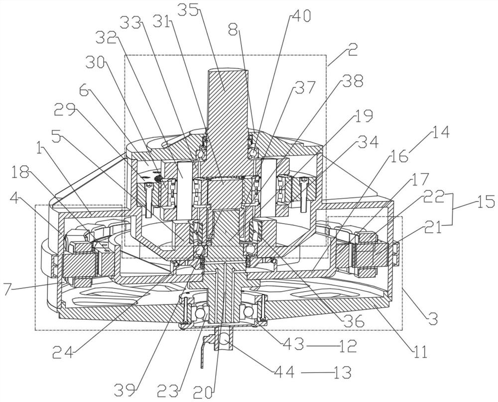
Vertical semi-direct-drive permanent magnet synchronous motor
A permanent magnet synchronous motor, semi-direct drive technology, applied in synchronous motors with stationary armatures and rotating magnets, motors, electric components, etc. The effect of meeting the installation and use requirements of the host, reducing centrifugal force and gravity, and low manufacturing and operation and maintenance costs
- Summary
- Abstract
- Description
- Claims
- Application Information
AI Technical Summary
Problems solved by technology
Method used
Image

Examples
Embodiment Construction
[0022] First of all, the original design intention of the present invention is explained. Most of the existing mills, mixers and other equipment that require vertical power input use the "asynchronous motor + coupling + multi-stage vertical gear device" drive device, which has complex structure and high manufacturing cost. , low efficiency, insufficient reliability and other protruding problems, the oil leakage problem of the existing vertical gear device occurs from time to time, the vertical semi-direct drive permanent magnet synchronous motor planetary gear device adopts oil pool lubrication, and there is a risk of oil leakage. After the gear device leaks oil, the lubricating oil enters the motor, and the lubricating oil will corrode the stator windings, reduce the insulation of the windings, and easily lead to faults such as winding leakage, short circuit, and even fire; if the lubricating oil leaks from the output shaft end, it will pollute the The work site affects produc...
PUM
 Abstract
Description
Claims
Application Information