Control system of wind turbine generator

A technology for wind turbines and control systems, applied in control systems, wind power generation, control generators, etc., can solve problems such as overcurrent and overvoltage, accelerated stator flux DC component attenuation, and weak unit fault ride-through ability, etc. Effects of small peak value, accelerated attenuation, and improved fault ride-through capability

Pending Publication Date: 2022-05-27
HUANENG CLEAN ENERGY RES INST +1
View PDF0 Cites 0 Cited by
  • Summary
  • Abstract
  • Description
  • Claims
  • Application Information

AI Technical Summary

Problems solved by technology

[0002] At present, wind turbines have been widely used in power generation. Among them, wind turbines are very sensitive to grid faults. In the event of a fault, the machine-side converter has limited ability to control the doubly-fed generator, resulting in weak fault ride-through capability of the unit. Therefore, in order to ensure safe operation, wind turbines must have low-voltage ride-through capability
[0003] However, in related technologies, when the grid voltage drops and fails, the rotor of the doubly-fed generator set will experience over-current and over-voltage phenomena. For mild voltage drops, the control strategy is often improved and the de-excitation control is used to achieve fault ride-through operation. The rotor magnetic field cancels the transient component in the stator magnetic field, accelerates the attenuation of the DC component of the stator flux linkage to limit the large stator and rotor current during the fault process
However, the aforementioned techniques cannot accelerate the attenuation of the transient flux linkage and cannot reduce the peak value of the rotor current

Method used


Image

  • Control system of wind turbine generator
  • Control system of wind turbine generator
  • Control system of wind turbine generator

Examples


Embodiment Construction

[0024] Exemplary embodiments of the present application are described below with reference to the accompanying drawings, which include various details of the embodiments of the present application to facilitate understanding, and should be considered as exemplary only. Accordingly, those of ordinary skill in the art will recognize that various changes and modifications of the embodiments described herein can be made without departing from the scope and spirit of the present application. Also, descriptions of well-known functions and constructions are omitted from the following description for clarity and conciseness.

[0025] Hereinafter, the control system of the wind turbine of the present application will be described in detail by using the embodiments.

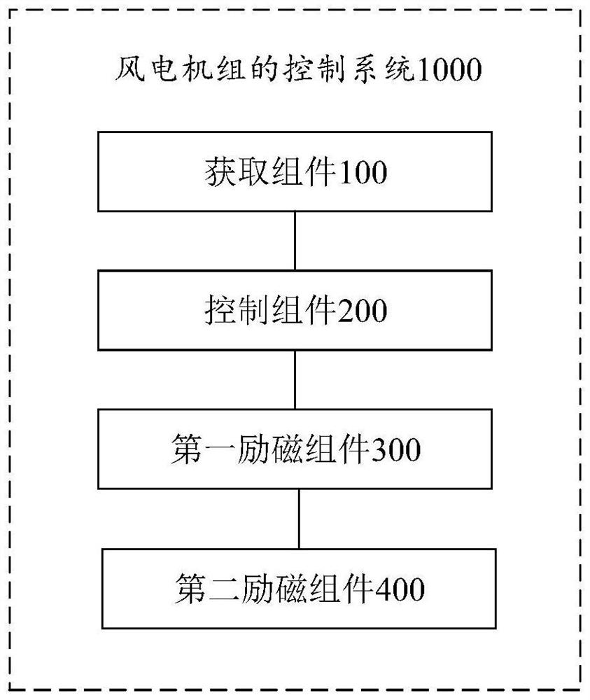
[0026] figure 1 This is a schematic structural diagram of the control system of the wind turbine according to the embodiment of the present application.

[0027] like figure 1 As shown, the control system 1000 of the wi...


PUM


Abstract

The invention provides a control system of a wind turbine generator, the control system is arranged in the wind turbine generator, and the system comprises an acquisition assembly, a control assembly, a first excitation control assembly and a second excitation control assembly; the acquisition component is used for acquiring a voltage amplitude of a converter group corresponding to the wind turbine generator and a voltage threshold value corresponding to a low voltage ride-through state of the wind turbine generator; in response to the fact that the voltage amplitude is smaller than the voltage threshold value, a first control instruction is generated and sent to the control assembly; and the control assembly is used for receiving the first control instruction and accessing the first excitation control assembly and the second excitation control assembly according to the first control instruction so as to perform excitation control on the wind turbine generator through the first excitation control assembly and the second excitation control assembly. The introduction of the second excitation control assembly increases the equivalent resistance of the rotor side equivalent circuit, accelerates the attenuation of the transient flux linkage, reduces the peak value of the rotor current in the voltage drop process, and improves the fault ride-through capability of the wind turbine generator.

Description

technical field [0001] The invention relates to the technical field of power generation, in particular to a control system of a wind turbine. Background technique [0002] At present, wind turbines have been widely used in power generation. Among them, wind turbines are very sensitive to grid faults. In the event of a fault, the machine-side converter has limited control capability of the doubly-fed generator, resulting in a weaker fault ride-through capability of the unit. Therefore, in order to ensure safe operation, wind turbines must have low voltage ride-through capability. [0003] However, in the related art, when a grid voltage sag fault occurs, the rotor of the DFIG generator set will appear overcurrent and overvoltage. For mild voltage sag, the control strategy is often improved, and de-excitation control is used to achieve fault ride-through operation. The rotor magnetic field cancels the transient components in the stator magnetic field, and accelerates the atte...

Claims


Application Information

Patent Timeline
Patent Type & Authority Applications(China)
IPC IPC(8): H02P9/12H02P101/15
CPCH02P9/123H02P2101/15Y02E10/76
Inventor 张俊杰王峰辉马宁超李剑武郭超马帅张洋焦冲蔡安民
Owner HUANENG CLEAN ENERGY RES INST
Why Eureka
Try Eureka