Lower limb vein radiography device and method for venous thrombosis detection
A technique for venous thrombosis and lower extremity, which is applied in the field of lower extremity venography devices for venous thrombosis detection, can solve the problems of affecting the imaging effect and extrusion, and achieves the effect of improving the imaging effect and avoiding extrusion.
- Summary
- Abstract
- Description
- Claims
- Application Information
AI Technical Summary
Problems solved by technology
Method used
Image
Examples
Embodiment 1
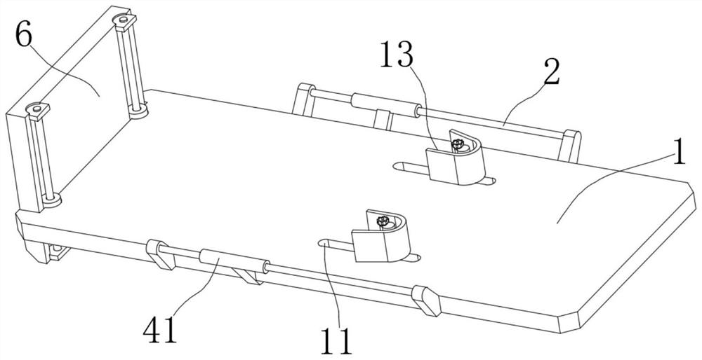
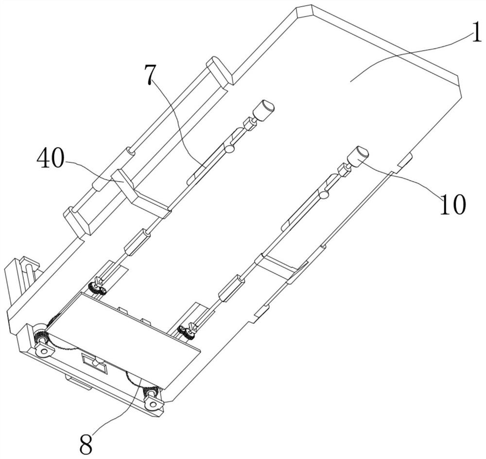
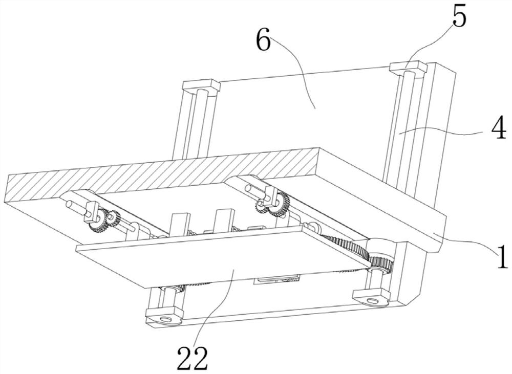
[0030] see Figure 1-Figure 3 , a lower extremity phlebography apparatus for detecting venous thrombus in the figure, including an examination bed 1, with support bars 2 fixed on both sides of the examination bed 1, and two rotating sleeves 3 that are rotatably installed at the tail end of the examination bed 1. On the support mechanism 7 on the examination bed 1 and the linkage mechanism 8 installed on the bottom of the examination bed 1, the adjustment rod 4 is threadedly inserted into the two rotating sleeves 3, and the two ends of the two adjustment rods 4 are rotated and installed with connecting plates 5, and the backing plate 6 is fixed through the connecting plate 5, the supporting mechanism 7 is used for auxiliary support to the patient, and the linkage mechanism 8 is used for adjusting the position of the backing plate 6.
[0031] It should be noted that: in this scheme, the designed support mechanism 7 and linkage mechanism 8 are installed on the examination bed 1, ...
Embodiment 2
[0046] see Figure 7 with Figure 8 , this embodiment is further described for Example 1. The support member 13 in the illustration includes an arc-shaped plate 14, and an adjustment shaft 15 is fixed inside the arc-shaped plate 14, and the adjustment shaft 15 slides through the support rod 12. One side of the adjustment shaft 15 A tooth plate 16 is fixed, and a limiting groove 17 is opened on the other side. A limiting block 18 matching the limiting groove 17 is fixed in the support rod 12, and a rotating shaft 19 is inserted in the supporting rod 12 for rotation, and the rotating shaft The bottom end of 19 is fixed with the adjustment gear 20 meshed with the tooth plate 16, and the top is fixed with a rotary cap 21;
[0047] It should be noted that: the arc-shaped plate 14 can support the patient's armpits. When supporting people of different sizes, considering the improvement of comfort, the design of the sliding plug and the adjustment shaft 15 in the support rod 12 allow...
Embodiment 3
[0049] see Image 6 , this embodiment is further described for other embodiments, the backing plate 6 in the illustration is provided with an adjustment port 34, and a mounting plate 35 is fixed in the adjustment port 34, and a moving rod 36 is slidably inserted into the mounting plate 35, and the moving The outer end of the bar 36 is fixed with an arc-shaped block 37, and the linkage table 22 is fixed with an abutment plate 38 contacting the tail end of the moving bar 36, and the outer side of the moving bar 36 is covered with a push-off spring 39 for pushing the arc-shaped block 37 to move outward. ;
[0050] It is worth noting that: in order to make the contact between the tail end of the moving rod 36 and the abutment plate 38 more stable, the tail end of the moving rod 36 is designed to be fixed with a ball 42 .
[0051] It should be noted that: when the examination bed 1 is in a vertical state, the backing plate 6 is in direct contact with the ground, thereby pressing t...
PUM
 Abstract
Description
Claims
Application Information
 - R&D
- Intellectual Property
- Life Sciences
- Materials
- Tech Scout
- Unparalleled Data Quality
- Higher Quality Content
- 60% Fewer Hallucinations
Browse by: Latest US Patents, China's latest patents, Technical Efficacy Thesaurus, Application Domain, Technology Topic, Popular Technical Reports.
© 2025 PatSnap. All rights reserved.Legal|Privacy policy|Modern Slavery Act Transparency Statement|Sitemap|About US| Contact US: help@patsnap.com


