Sparse array arrangement method for direction of arrival estimation

A direction-of-arrival estimation and sparse array technology, which is applied to direction finders using radio waves, radio wave direction/deviation determination systems, antenna arrays, etc., can solve problems such as gaps, and achieve the effect of improving accuracy and resolution

Pending Publication Date: 2022-05-31
NORTHWEST UNIV
View PDF0 Cites 0 Cited by
  • Summary
  • Abstract
  • Description
  • Claims
  • Application Information

AI Technical Summary

Problems solved by technology

However, these arrays often show performance close to the minimum redundant array in the array with a small number of array elements, but in the case of a large number of ar

Method used


Image

  • Sparse array arrangement method for direction of arrival estimation
  • Sparse array arrangement method for direction of arrival estimation
  • Sparse array arrangement method for direction of arrival estimation

Examples


Embodiment 1

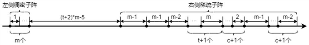
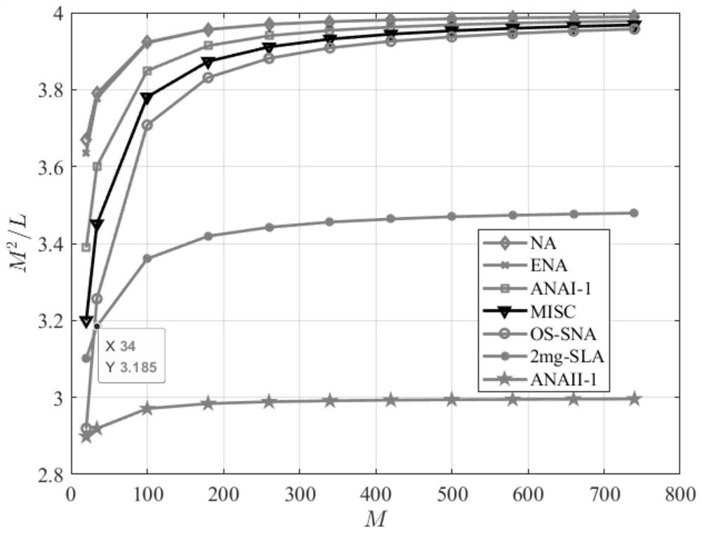
[0064] The purpose of this example is to verify that the sparse array proposed in the present invention has a larger aperture and a higher degree of spatial freedom under the same array element compared with the other five arrays, and is closer to the performance of ANAII-1. It is supplemented that, for M array elements, a uniform linear array with a spacing of half a wavelength can perform direction finding on M-1 source signals at the same time, and M-1 is the size of the spatial degree of freedom. The definition of the linear array aperture is the maximum array element interval, which is equal to (M-1)×d in the above uniform linear array, and we find that the difference between the two is only unit d in value. For sparse arrays, the spatial degrees of freedom are determined by the corresponding virtual array. The array proposed in this paper and all the comparison arrays, the physical arrays are all sparse arrays. After virtual change, a virtual array with the same aperture...

Embodiment 2

[0070] The purpose of this example is to verify that the array proposed in the present invention has better direction finding performance under the same array element compared with the other five arrays, and is closer to the performance of ANAII-1. It is assumed that there are 61 uncorrelated sources in the space incident on the above sparse array, and the incident angles are uniformly distributed between -60° and 60°. The signal-to-noise ratio of the incident signal was changed from -20dB to 20dB, the step size was 2dB, there were 21 points in total, the sampling number was K=1000, and 100 Monte Carlo experiments were carried out.

[0071] The optimal parameter settings and apertures of each array in the case of 34 elements are as follows:

[0072]

[0073] The root mean square error of seven sparse arrays for DOA estimation varies with the signal-to-noise ratio as follows: Figure 4 shown. It can be seen that the SNR of all arrays is between -20dB and 0dB. With the incr...

Embodiment 3

[0075] The purpose of this example is to verify that the array proposed in the present invention has better direction finding performance under the same array element compared with the other five arrays, and is closer to the performance of ANAII-1. It is assumed that there are 61 uncorrelated sources in the space incident on the above sparse array, and the incident angles are uniformly distributed between -60° and 60°. The signal-to-noise ratio of the incident signal is 0dB, and 100 Monte Carlo experiments are carried out. The variation of the sampling number is set to non-uniform sampling, and the sampling is performed in small steps and multi-sampling in the interval of low sampling number, and sampling in large step in the interval of high sampling number. method, the final set of sampling numbers is:

[0076] {50, 100, 150, 200, 250, 300, 400, 600, 800, 1000, 1300, 1600, 1900, 2400, 2800}, a total of 15 points.

[0077] The parameter settings of each array are the same as...


PUM


Abstract

The invention discloses a sparse array arrangement method for direction of arrival estimation, which comprises the following steps of: on the basis of a nested array, reserving a dense sub-array of which the left-side interval is half-wavelength of an incident signal, rearranging a right-side sparse sub-array, setting a larger interval between the left-side sub-array and the right-side sub-array, and determining the size of the interval by the arrangement of the right-side sub-array. The method comprises the basic steps of determining the number of array elements of an array, obtaining parameters of the array through an array aperture maximization configuration formula, then substituting the parameters into an array general term formula, determining a spacing set of the array elements, and finally converting the spacing set of the array elements into an array element position set. Compared with a traditional sparse array improved based on a nested array, the design method effectively improves the aperture of the array under the condition that the number of array elements is the same, and improves the precision of direction of arrival estimation of the array at the same time. Particularly, the design method provided by the invention is more obvious in improvement of the array direction finding performance for the array with more (more than or equal to 26) array elements.

Description

technical field [0001] The invention belongs to the field of array antenna design, in particular to a sparse array arrangement method for direction of arrival estimation, which can be used for active and passive multi-target direction finding. The array is converted into a virtual array with additional elements, thereby improving the array's DF performance. Background technique [0002] The traditional subspace-based direction of arrival estimation algorithm uses a uniform linear array of N elements, which can simultaneously find directions of up to N-1 targets, and it is limited by the Nyquist sampling theorem, that is, it can be expressed in the airspace. Therefore, the spacing between adjacent array elements cannot be greater than the half wavelength of the incident signal. In practical applications, the array element spacing of a uniform linear array is fixed at half wavelength, which leads to a strong mutual coupling effect between the array elements, and the array ape...

Claims


Application Information

Patent Timeline
IPC IPC(8): G01S3/14H01Q21/00
CPCG01S3/14H01Q21/00Y02D30/70
Inventor 李舰朱从光聂卫科徐鹏飞侯爱琴牛进平王薇王安文王夫蔚
Owner NORTHWEST UNIV
Why Eureka
Try Eureka