Shadow mask and manufacturing method thereof

a manufacturing method and shadow mask technology, applied in the field of shadow masks, can solve the problems of difficult to design shadow masks with fine pitches or patterns using conventional manufacturing technologies, and difficult to manufacture shadow masks with precise sizes. , to achieve the effect of producing a shadow mask, reducing the amount of side etching, and improving the precision and resolution of patterns

Active Publication Date: 2011-08-30
LG DISPLAY CO LTD
View PDF6 Cites 1 Cited by
  • Summary
  • Abstract
  • Description
  • Claims
  • Application Information

AI Technical Summary

Benefits of technology

[0008]An object of the present invention is to provide a shadow mask having fine slits, thereby having an advantage of improving precision and resolution of patterns by reducing the amount of side etching when etching a mask substrate.
[0009]Another object of the present invention is to provide a manufacturing method of a shadow mask capable of effectively producing a shadow mask having the above described advantage.

Problems solved by technology

Therefore, it is difficult to manufacture a shadow mask having slits or slots with precise sizes.
Further, it is difficult to manufacture a shadow mask having slits or slots with substantially uniform sizes along the vertical direction of the mask.
Further, since there can be severe process errors in the shadow mask manufacturing method according to the related art, it is difficult to design a shadow mask with fine pitches or patterns using the conventional manufacturing technologies.

Method used


Image

  • Shadow mask and manufacturing method thereof
  • Shadow mask and manufacturing method thereof
  • Shadow mask and manufacturing method thereof

Examples


Embodiment Construction

[0022]Reference will now be made in detail to the preferred embodiments of the present invention, examples of which are illustrated in the accompanying drawings.

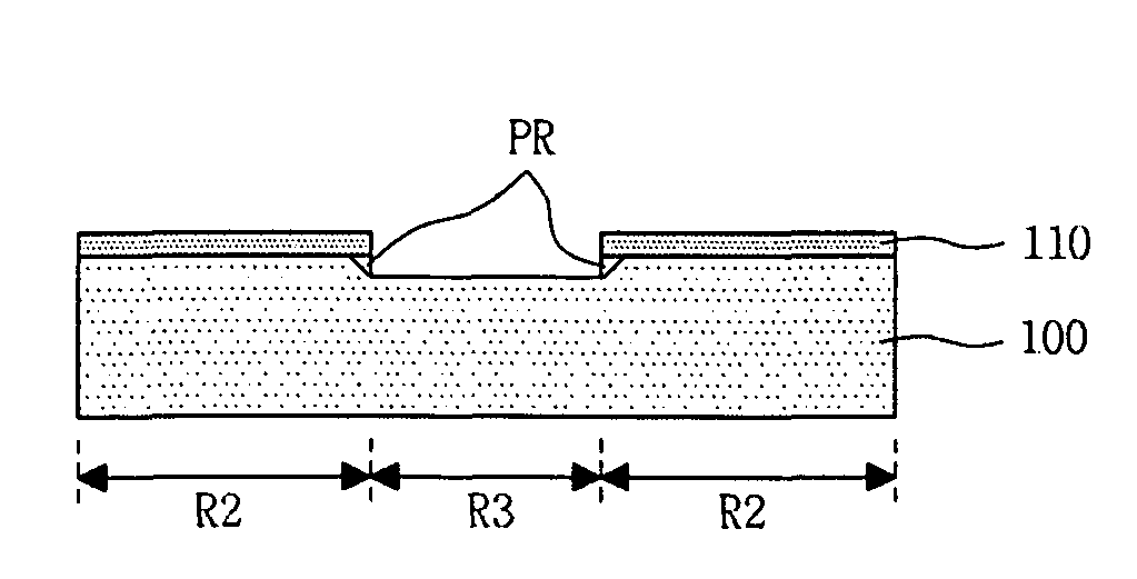
[0023]FIG. 6 is a cross sectional view illustrating a part of the shadow mask according to one embodiment of the present invention. The shadow mask according to the embodiment shown in FIG. 6 of the present invention comprises a mask substrate 100 made of iron (Fe) or iron-nickel alloy (Fe—Ni alloy). The mask substrate 100 comprises a slit region R3 and a shadow region R2. The slit region R3 has one or more slits, each formed through the mask substrate 100. The shadow region R2 is a region other than the slit region R3. During the manufacturing process of the shadow mask, the slit region R3 in the mask substrate 100 undergoes an etching process, while the shadow region R2 in the mask substrate 100 does not undergo an etching process. Each of respective sides of the slit region R3 has a plurality of undercut portions, each ha...


PUM

PropertyMeasurementUnit
thicknessaaaaaaaaaa
thickaaaaaaaaaa
thicknessaaaaaaaaaa

Abstract

Disclosed is a shadow mask having a fine slit that can improve precision and resolution of a pattern by reducing side etching during an etching process of a mask substrate, and a manufacturing method thereof. The shadow mask includes a mask substrate, a slit region formed by penetrating through the mask substrate, the slit region having a plurality of undercut portions at respective sides thereof, each undercut portion having a unit thickness, and a shadow region provided in the mask substrate, the shadow region corresponding to a region other than the slit region.

Description

[0001]The present invention claims the benefit of Korean Patent Application No. 10-2005-0057317 filed in Korea on Jun. 29, 2005, which is hereby incorporated by reference.BACKGROUND OF THE INVENTION[0002]1. Field of the Invention[0003]The present invention relates to a shadow mask, and a manufacturing method thereof.[0004]2. Discussion of the Related Art[0005]FIGS. 1 to 3 are cross sectional views for sequentially illustrating a method of manufacturing a shadow mask according to the related art. The shadow mask is applied to a liquid crystal display apparatus (LCD apparatus) or an organic light-emitting diode (OLED) in order to form printed patterns. According to the shadow mask manufacturing method in the related art, a photoresist pattern PR is formed on a mask substrate 10 as shown in FIG. 1. The mask substrate 10 is then wet etched using the photoresist pattern PR as an etching mask as shown in FIG. 2. The photoresist pattern PR on the mask substrate 10 is finally removed as sho...

Claims


Application Information

Patent Timeline
Patent Type & Authority Patents(United States)
IPC IPC(8): H01J29/07
CPCH05B33/10C23F1/02H01L21/0274
Inventor YOO, SOON SUNGKWON, OH NAM
Owner LG DISPLAY CO LTD
Why Eureka
Try Eureka