
Particle image speed measurement method and device based on global optimization

A particle image velocimetry, particle image technology, applied in measurement devices, fluid velocity measurement, velocity/acceleration/shock measurement, etc., can solve the problems of low spatial resolution of velocity field, noise, PIV flow field experimental error, etc. The effect of precision and resolution

Active Publication Date: 2020-09-22
INST OF MECHANICS - CHINESE ACAD OF SCI
View PDF6 Cites 0 Cited by
  • Summary
  • Abstract
  • Description
  • Claims
  • Application Information

AI Technical Summary

Problems solved by technology

However, limited by the experimental conditions and the algorithm itself, the flow field obtained by the cross-correlation algorithm still faces two major problems: noise and unsatisfactory resolution
When the size of the query window is large, the obtained velocity field is relatively smooth, but the spatial resolution of the velocity field is low due to the modulation of the window; when the size of the query window is small, although the velocity field with high spatial resolution can be obtained, the flow field contains More errors and bad points affect the further feature extraction of the flow field
Although PIV technology has been widely used in the study of fluid mechanics, it can be seen from the above analysis that the flow field obtained by PIV also has inherent shortcomings.
First, there are experimental errors and noises in the PIV flow field, which cannot fully satisfy the governing equation of fluid mechanics (N-S equation); second, the spatial resolution of the PIV flow field is limited by the size of the query window, and the small-scale flow structure cannot be fully resolved
For example, in a turbulent boundary layer, the velocity field calculated by PIV is not reliable near the wall due to the presence of velocity gradients and fewer tracer particles

Method used


Image

  • Particle image speed measurement method and device based on global optimization
  • Particle image speed measurement method and device based on global optimization
  • Particle image speed measurement method and device based on global optimization

Examples


Embodiment Construction

[0056] In order to make the purposes, technical solutions and advantages of the embodiments of the present application clearer, the technical solutions in the embodiments of the present application will be clearly and completely described below in conjunction with the drawings in the embodiments of the present application. Obviously, the described embodiments It is a part of the embodiments of this application, not all of them. Based on the embodiments in this application, all other embodiments obtained by persons of ordinary skill in the art without making creative efforts belong to the scope of protection of this application.

[0057] In order to facilitate the understanding of the embodiments of the present application, the following will further explain and illustrate with specific embodiments in conjunction with the accompanying drawings, and the embodiments do not constitute a limitation to the embodiments of the present application.

[0058] figure 1 It is a schematic ...


PUM


Abstract

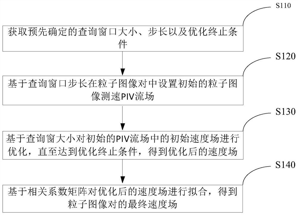
The embodiment of the invention relates to a particle image speed measurement method and device based on global optimization. The method comprises the steps of obtaining a predetermined query window size, a predetermined step length and a predetermined optimization termination condition; obtaining an initial particle image velocity measurement PIV flow field in a particle image pair based on the query window step length; optimizing an initial velocity field in the initial PIV flow field based on the size of the window until the optimization termination condition is reached to obtain an optimized velocity field, the PIV flow field comprising the initial velocity field and a correlation coefficient matrix; and fitting the optimized velocity field based on a correlation coefficient matrix toobtain a final velocity field of the particle image pair. Therefore, the precision and the resolution of the velocity field can be improved by globally optimizing the velocity field and fitting.

Description

technical field [0001] The embodiments of the present application relate to the field of experimental fluid mechanics, and in particular to a method and device for particle image velocimetry based on global optimization. Background technique [0002] Particle image velocimetry (PIV) technology can obtain the two-dimensional or three-dimensional velocity distribution of the flow field, and is an important means to quantitatively measure the complex flow field in experimental fluid mechanics. This technique belongs to non-contact measurement. During the experiment, tiny tracer particles that can follow the fluid movement are spread in the flow field, and these particles are uniformly distributed in the flow field and illuminated by a laser sheet light source or a sheet light source with sufficient brightness. The camera receives the light scattered by the tracer particles to form a particle image, and the acquisition time interval of two consecutive images (image pairs) is Δt...

Claims


Application Information

Patent Timeline
IPC IPC(8): G01P5/20G06F17/16
CPCG01P5/20G06F17/16
Inventor 王洪平王士召何国威
Owner INST OF MECHANICS - CHINESE ACAD OF SCI
Learn More