Buried high-temperature-resistant shielding cable

A shielded cable, high temperature resistant technology, applied in the field of buried high temperature resistant shielded cable, can solve the problems of cable core wire damage, cable connection trouble, cable bearing capacity is not good, etc., to improve the service life, wide range of use, Avoid the effect of abrasion

Inactive Publication Date: 2022-05-31
WUXI ZHONGHUI WIRE & CABLE
View PDF1 Cites 2 Cited by
  • Summary
  • Abstract
  • Description
  • Claims
  • Application Information

AI Technical Summary

Problems solved by technology

[0004] Some of the current buried cables only use bottom plates, side plates and partitions to protect the cables. These methods are not good for the bearing capacity of the cables, and it is easy to cause damage to the cable core due to stress between the cables, and It is also troublesome to connect cables, which affects the use of buried cables

Method used


Image

  • Buried high-temperature-resistant shielding cable
  • Buried high-temperature-resistant shielding cable
  • Buried high-temperature-resistant shielding cable

Examples


Embodiment 1

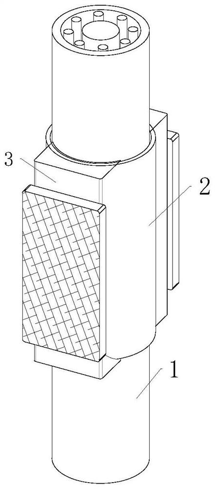
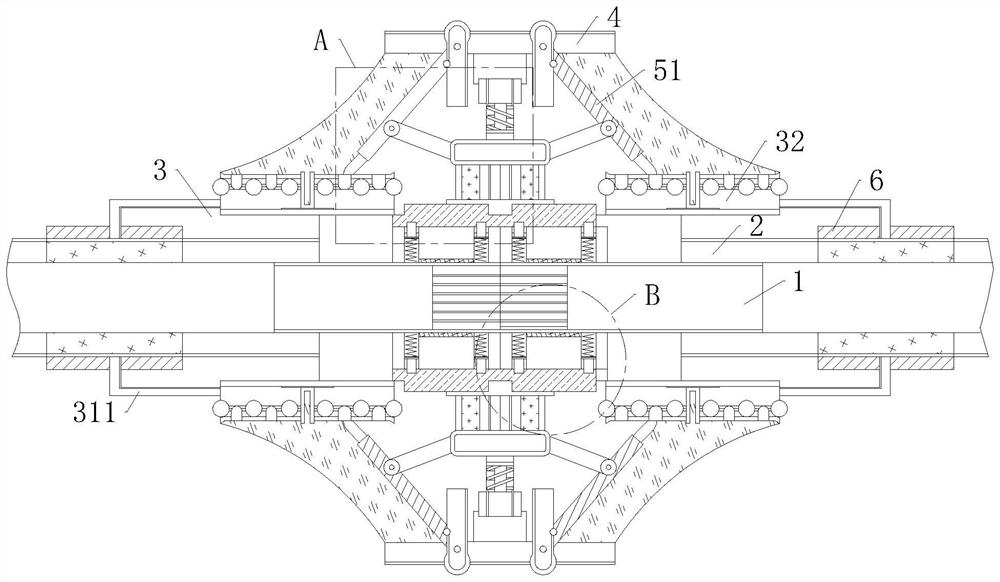
[0030] like figure 1 , figure 2 , image 3 , Figure 5 and Image 6 As shown in the embodiment of the present invention, a buried high temperature resistant shielded cable includes a cable body 1 and a connecting seat 2. The cable body 1 runs through the interior of the connecting seat 2, and the connecting A support base 3 is fixedly connected to the outer surface of the base 2, and a shielding base 4 is fixedly connected to the inside of the support base 3. The side surface of the shielding base 4 is provided with a connecting component 5, and one side of the connecting component 5 is connected There is an airtight assembly 6; in the present invention, when connecting two cables, the two cable heads are passed into the connection seat 2, and then the connection assembly 5 is used to connect the cables; the airtight assembly 6 can seal the cable connection. shield.

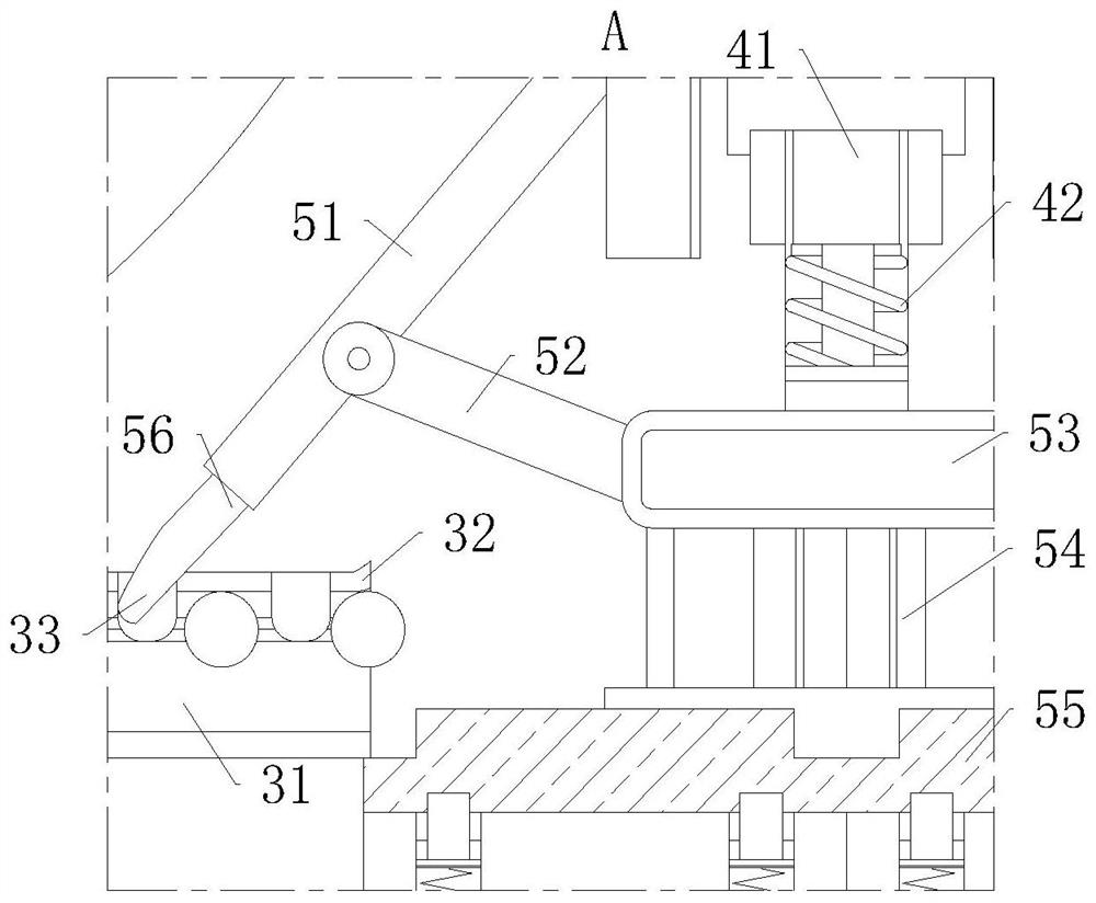
[0031] like figure 2 , image 3As shown in the figure, the connecting assembly 5 includes a toggle ro...

Embodiment 2

[0037] like figure 2 and Figure 4 As shown, Comparative Example 1, wherein another embodiment of the present invention is: the middle part of the outer surface of the connection seat 2 is fixedly connected with a gas transmission seat 21, and the interior of the gas transmission seat 21 is fixedly connected with a plurality of The heat supply pipe 22, the inside of the gas supply seat 21 is fixedly connected with a heat-conducting rod 23, the inside of the heat supply pipe 22 is provided with a piston rod 24, and the surface of the piston rod 24 is fixedly connected with a top rod 25, the said The surface of the ejector rod 25 is fixedly connected with a closed ring 26, and one side of the piston rod 24 is provided with a tension spring 27; when the electrical resistance of the cable joint increases due to external reasons, and the joint generates heat, the heat will be transmitted to the heat conduction. On the surface of the rod 23, when the heat is too high, the gas insi...


PUM


Abstract

The invention belongs to the technical field of shielding cables, and particularly relates to a buried high-temperature-resistant shielding cable which comprises a cable body and a connection seat, the cable body penetrates through the connection seat, a supporting seat is fixedly connected to the outer surface of the connection seat, and a shielding seat is fixedly connected to the interior of the supporting seat. A connection assembly is arranged on the side surface of the shielding seat, one side of the connection assembly is connected with a sealing assembly, the connection assembly comprises a poke rod rotationally connected with the side surface of the shielding seat, the outer surface of the poke rod is rotationally connected with a rotating rod, and one side of the rotating rod is connected with a push plate. When the rotating rod drives the push plate to move, the push plate can pull the telescopic rod and the extension spring on one side of the push plate at the same time, at the moment, the telescopic rod and the extension spring can reduce vertical loading force borne by the cable joint, the phenomenon that wires at the hinged position are damaged due to sudden stress of the cable joint is avoided, and the service life of the cable is prolonged.

Description

technical field [0001] The invention belongs to the technical field of shielded cables, in particular to a buried high temperature resistant shielded cable. Background technique [0002] The structure of the cable generally includes the outer protective layer of the cable and the core wire of the cable. In order to increase the safety of the core wire of the cable, some buried cables now require the outer layer of the cable to have better shear resistance and extrusion resistance. Especially direct buried cables. [0003] In order to ensure that the buried cable has better anti-shear and anti-extrusion capabilities, some solutions have also been proposed in the prior art. For example, a Chinese patent with publication number CN107979055A discloses a buried cable protection device, which includes Bottom plate; side plates located on both sides of the bottom plate, the side plates are supported by the bottom plate; mounting holes arranged on both sides of the side plate; The...

Claims


Application Information

Patent Timeline
Patent Type & Authority Applications(China)
IPC IPC(8): H01B7/29H01B7/42H01R13/52H01R13/56H01R13/58
CPCH01R13/5804H01R13/5837H01R13/56H01R13/5221H01B7/421H01B7/29Y02A30/14
Inventor 邱国军
Owner WUXI ZHONGHUI WIRE & CABLE
Why Eureka
Try Eureka