SVG-based deep well non-coal mine electrified railway power supply system and use method thereof

A technology for electrified railways and power supply systems, which is applied to AC networks to reduce harmonics/ripples, reduce/prevent power oscillations, adjust/eliminate/compensate reactive power, etc., and can solve problems such as grid resonance and poor dynamic performance. Achieve the effect of strong adaptability, fast governance speed and high reliability

Pending Publication Date: 2022-05-31
KUNMING UNIV OF SCI & TECH
0 Cites 0 Cited by

AI-Extracted Technical Summary

Problems solved by technology

However, when using capacitors for reactive power compensation, the ...

Method used

Because Us2 and R are all positive in the formula, so angle δ is proportional to reactive power Q, and when δ was less than 0, SVG input inductive reactive power to system; when δ was greater than 0, SVG input capacitive power to system Reactive power, through reactive power compensation to maintain power balance and improve voltage stability.
The basic reali...

Abstract

The invention relates to an SVG-based deep well non-coal mine electrified railway power supply system and a use method thereof, and belongs to the technical field of mining industry electricity. The system is composed of an alternating current power supply system, an SVG device, a traditional LCC converter station and a traction network power transmission system. According to the method, high-power-factor operation of the deep-well non-coal-mine electrified railway power supply system can be achieved, the transient stability of the power grid voltage is effectively improved, voltage treatment of the traction network of the deep-well non-coal-mine electrified railway power supply system is achieved, and the method is higher in reliability, free of harmonic pollution and higher in environment adaptability.

Application Domain

Polyphase network asymmetry elimination/reductionReactive power adjustment/elimination/compensation +3

Technology Topic

Automotive engineeringProcess engineering +9

Image

  • SVG-based deep well non-coal mine electrified railway power supply system and use method thereof
  • SVG-based deep well non-coal mine electrified railway power supply system and use method thereof
  • SVG-based deep well non-coal mine electrified railway power supply system and use method thereof

Examples

  • Experimental program(2)

Example Embodiment

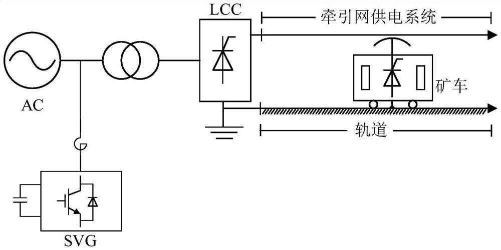
[0058] Embodiment 1: apply the present invention in PSCAD, build as figure 2 The simulation model of the deep well non-coal mine electrified railway power supply system with dynamic SVG reactive power compensation device is shown. The voltage level of the AC power supply system is 115kV. is 0.01Ω, the moment of failure is 1s, the duration is 1s, and the sampling rate is 20KHz. The specific process of implementation is as follows:
[0059] 1. When a three-phase ground fault occurs on the AC side, the Figure 4 and Image 6 It can be seen that the DC voltage drops instantly, and the system current rises rapidly. At this time, the monitoring and fault diagnosis unit detects the system current information and transmits it to the control chip.
[0060] 2. The control chip detects that the system current is too high, and the controller and the drive and protection circuit give the drive information for reactive power compensation.
[0061]3. The inverter circuit in the device receives feedback, compensates the reactive power and increases the voltage, such as Figure 4 and Figure 5 As shown, at 1s, the SVG device detects the voltage drop and compensates the reactive power until the fault ends at 2s, the DC voltage rises at this stage, and the DC voltage reaches the system requirements after the fault ends at 2s, the SVG device exits operation, and the DC The voltage returned to normal and remained stable.
[0062] According to the results obtained in this example, it is shown that the SVG-based deep well non-coal mine electrified railway power supply system traction network voltage control method and system provided by the present invention can still dynamically adjust the system reactive power when a fault occurs, effectively improving the grid voltage stability.

Example Embodiment

[0063] Embodiment 2: apply the inventive method in PSCAD, build as figure 2 The simulation model of the power supply system of the deep mine non-coal mine electrified railway with dynamic SVG reactive power compensation device shown, the voltage level of the AC power supply system is 115kV, the SVG device is connected in parallel on the AC side, and a three-phase ground fault occurs on the AC side. For the reactive power compensation capability of the method and system of the present invention in a high-resistance fault state, the transition resistance is set to 300Ω, the fault occurrence time is 1s, the duration is 1s, and the sampling rate is 20KHz. The specific process of implementation is as follows:
[0064] 1. When a three-phase ground fault occurs on the AC side, the Figure 7 and Figure 9 It can be seen that the DC voltage drops instantly, and the system current rises rapidly. At this time, the monitoring and fault diagnosis unit detects the system current information and transmits it to the control chip.
[0065] 2. Due to the high-resistance three-phase grounding fault in the system, the sudden change of the fault voltage and current becomes smaller, but the control chip still detects that the system current is too high and sends a signal, and the controller and the drive and protection circuit give reactive power compensation driver information.
[0066] 3. The inverter circuit in the device receives feedback, compensates the reactive power and increases the voltage, such as Figure 7 and Figure 8 As shown, at 1s, the SVG device detects the voltage drop and compensates the reactive power until the fault ends at 2s, the DC voltage rises at this stage, and the DC voltage reaches the system requirements after the fault ends at 2s, the SVG device exits operation, and the DC The voltage returned to normal and remained stable.
[0067] According to the results obtained in this example, it is shown that the SVG-based deep-well non-coal mine electrified railway power supply system traction network voltage control method and system provided by the present invention can dynamically adjust the system reactive power when a fault occurs, effectively improve the grid voltage stability, and be immune to high impact of faults.

PUM

no PUM

Description & Claims & Application Information

We can also present the details of the Description, Claims and Application information to help users get a comprehensive understanding of the technical details of the patent, such as background art, summary of invention, brief description of drawings, description of embodiments, and other original content. On the other hand, users can also determine the specific scope of protection of the technology through the list of claims; as well as understand the changes in the life cycle of the technology with the presentation of the patent timeline. Login to view more.

Similar technology patents

Airborne vision enhancement method and device

InactiveCN102063704Agood visual effectadaptable
Owner:CHINESE AERONAUTICAL RADIO ELECTRONICS RES INST

DC power real-time liftable capability calculation method

ActiveCN107342587AImprove transient stabilityavoid mismatch
Owner:NARI TECH CO LTD +3

System and method for improving transient stability of grid-connected wind generator system

ActiveUS11509138B1improve transient stabilityuse cost be save
Owner:ALI MOHD HASAN

Metal pipeline notch burr grinding device for machining

Owner:惠州市豪美仕智能技术有限公司

Classification and recommendation of technical efficacy words

  • Adaptable
  • Improve transient stability

Measuring system of three-dimensional shape of strong reflecting surface based on high dynamic strip projector

ActiveCN102937425AadaptableOvercome the influence of background light on measurement
Owner:BEIHANG UNIV

Production method of low-cost X52 pipeline steel and pipeline steel

ActiveCN103572025ASimple production process controladaptable
Owner:攀钢集团西昌钢钒有限公司 +1

DC power real-time liftable capability calculation method

ActiveCN107342587AImprove transient stabilityavoid mismatch
Owner:NARI TECH CO LTD +3

System and method for improving transient stability of grid-connected wind generator system

ActiveUS11509138B1improve transient stabilityuse cost be save
Owner:ALI MOHD HASAN
Why Eureka
Try Eureka