Leg fracture reduction machine

A leg and frame technology, applied in the field of leg fracture reduction machines, can solve the problems of difficult reduction, angular displacement, high price, etc., and achieve the effects of avoiding secondary injuries, meeting reduction requirements, and having a simple structure.

Pending Publication Date: 2022-06-03
班红梅
View PDF13 Cites 0 Cited by
  • Summary
  • Abstract
  • Description
  • Claims
  • Application Information

AI Technical Summary

Problems solved by technology

[0003] Due to the stretching of the surrounding muscles after fracture, the fracture end is likely to lead to shortening of the backbone and angular displacement. It is often difficult to achieve satisfactory results in manual reduction during operation, especially for patients with trauma for more than one week. length, the reduction state still cannot be maintained; how to use the indirect reduction technique to achieve a satisfactory fracture reduction effect and maintain the reduction state, and facilitate the minimally invasive implantation of the intramedullary nail has always been a difficult point in the closed reduction intramedullary nail fixation technology; Under technical conditions, traction beds are often used clinically to stretch broken bones, and the assistants who operate the traction beds need to be constantly adjusted according to the instructions of the chief surgeon. In addition, the existing traction beds are mostly manually adjusted, without quantitative standards, which is not conducive to the standardization and standardization of operations, and is expensive, which is not conducive to popularization in small and medium hospitals. Therefore, the leg fracture reduction proposed by the present invention machine has obvious meaning

Method used


Image

  • Leg fracture reduction machine
  • Leg fracture reduction machine
  • Leg fracture reduction machine

Examples


Embodiment Construction

[0021] The present invention will be further described below with reference to specific embodiments. The exemplary embodiments and descriptions of the present invention are used to explain the present invention, but are not intended to limit the present invention.

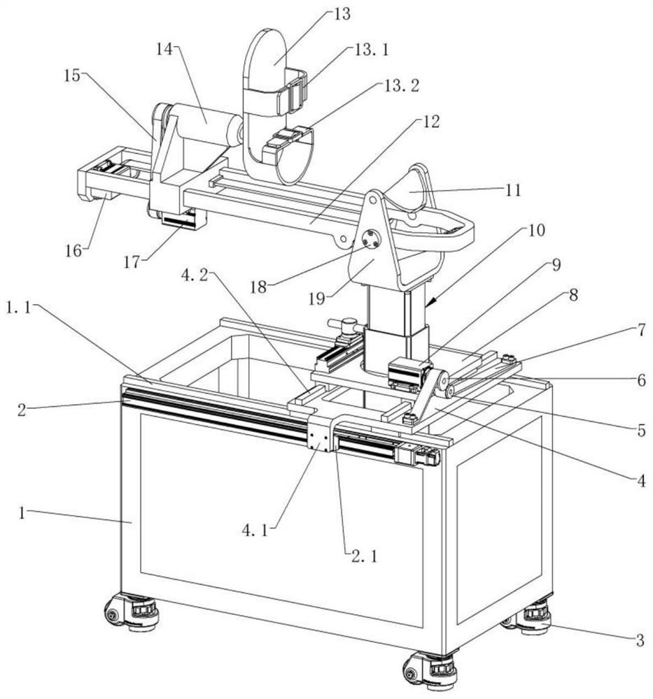
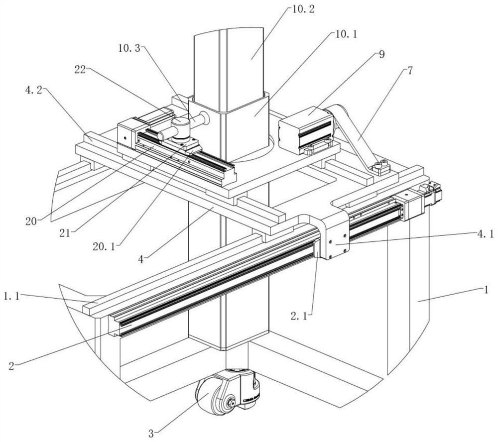
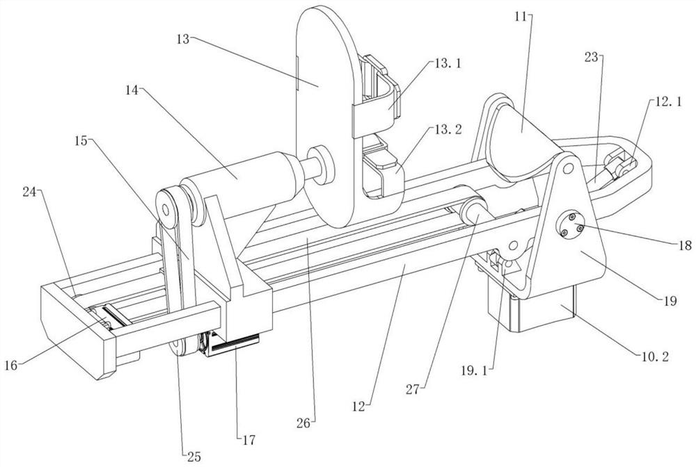
[0022] like figure 1 As shown in the figure, a leg fracture reduction machine includes a frame 1, a first sliding table 2, a Fuma wheel 3, a vertical sliding plate 4, a guide wheel 5, a first driving wheel 6, a first synchronous belt 7, and a horizontal sliding plate 8 , the first motor 9, the lifting column 10, the support plate 11, the vertical guide frame 12, the foot frame 13, the carriage 14, the third timing belt 15, the second motor 16, the third motor 17, the fixed shaft 18, the U-shaped frame 19. The second sliding table 20, the traverse table 21, the dial shaft 22, the electric cylinder 23, the second driving wheel 24, the third driving wheel 25, the second timing belt 26, the first driven wheel 27, the t...


PUM


Abstract

Four Foma wheels are installed on the lower side of a rack, a first sliding table can drive a longitudinal sliding plate to move front and back, a first motor can drive a transverse sliding plate to transversely move, a lifting column is installed on the transverse sliding plate and forms a rotating pair, and a longitudinal guide frame is rotationally connected with a U-shaped frame at the top end of the lifting column; the electric cylinder can drive the longitudinal guide frame to rotate in a pitching mode, the supporting plate can support the legs of a patient and is rotationally installed at the upper end of the U-shaped frame, the sliding frame is installed on the upper side of the longitudinal guide frame and forms a sliding pair, and the second motor can drive the sliding frame to move longitudinally through the second synchronous belt. The ring type pressure sensor and the plane thrust bearing are both coaxially installed at the upper end of the sliding frame with the rotating shaft, the telescopic rod and the rotating shaft form a spline transmission structure, the foot stool is used for fixing the foot of a patient and fixedly connected with the telescopic rod, and the third motor can drive a longitudinal shaft of the foot stool to rotate. And the control system is used for controlling the electrified operation of the leg fracture reduction machine, establishing a personal file of a patient, formulating a reduction scheme and recording reduction data.

Description

technical field [0001] The invention relates to the technical field of medical devices, in particular to a leg fracture reduction machine. Background technique [0002] Tibial and fibular shaft fractures are the most common fracture types in clinic, accounting for 24% of adult body fractures. All types of fractures except crack fractures require surgical treatment. The traditional surgical method is to use open reduction and internal fixation to treat the fracture site. In most cases, steel plates are used as internal fixators to integrate the bones when they heal. However, after surgery, the incision is prone to infection due to the exposure of the incision, the destruction of the biological environment of the fracture end, and the decline in the ability of soft tissue to resist infection. , internal fixation exposure, delayed fracture healing, poor reduction and other phenomena, so in the process of clinical surgery, the focus of surgery is to improve the fracture healing ...

Claims


Application Information

Patent Timeline
Patent Type & Authority Applications(China)
IPC IPC(8): A61B17/88
CPCA61B17/8866
Inventor 班红梅
Owner 班红梅
Why Eureka
Try Eureka