Lifting stacking machine with starting assembly

A component and transmission cavity technology, which is applied in the direction of unstacking of objects, stacking of objects, manipulators, etc., can solve the problems of cargo extrusion, re-finding effort, lack of position information, etc., to avoid slipping and avoid excessive clamping force big effect

Inactive Publication Date: 2022-06-03
SHENZHEN GUANHAO IND EQUIP
View PDF0 Cites 3 Cited by
  • Summary
  • Abstract
  • Description
  • Claims
  • Application Information

AI Technical Summary

Problems solved by technology

[0004] The purpose of the present invention is to solve the problem that the stacker existing in the prior art is extremely easy to over-press the goods, resulting in damage to the goods, and the stacked goods cannot be scanned and registered in time during the stacking process. As a result, the lack of position information after the goods are stacked, and the disadvantages of laborious searching, and a lifting stacker with a starting component is proposed

Method used


Image

  • Lifting stacking machine with starting assembly
  • Lifting stacking machine with starting assembly
  • Lifting stacking machine with starting assembly

Examples


Embodiment 1

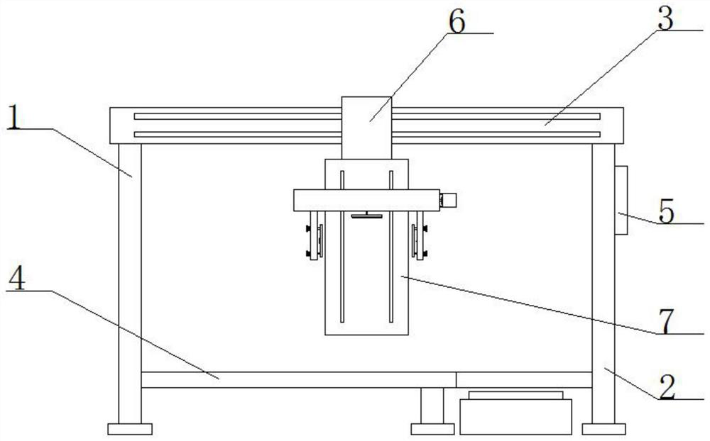
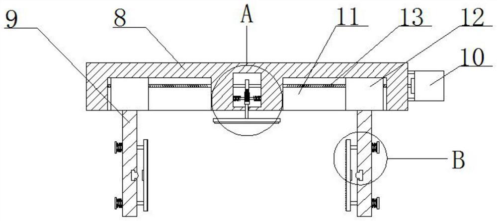
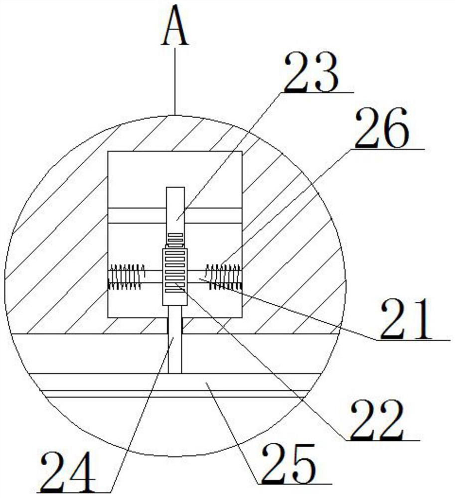
[0027] refer to Figure 1-5 , a lifting stacker with a start-up assembly, comprising a first support column 1 and a second support column 2, the top ends of the first support column 1 and the second support column 2 are fixedly connected with the same crossbar 3 by welding, and The first support column 1 and the second support column 2 are provided with the same stacking plate 4, the stacking plate 4 is provided with an operation port, the second supporting column 2 is provided with a PLC controller 5, and the cross bar 3 slides on A moving plate 6 is installed, the bottom of the moving plate 6 is fixedly connected with a side plate 7 by welding, a top plate 8 is slidably installed on one side of the side plate 7, and two clamping plates 9 are slidably installed at the bottom of the top plate 8. The plate 9 is provided with a buffering force-limiting mechanism, the bottom of the top plate 8 is provided with a scanning mechanism, one side of the top plate 8 is fixedly installed...

Embodiment 2

[0037] The difference from the first embodiment is that it includes a first support column 1 and a second support column 2, the top ends of the first support column 1 and the second support column 2 are fixedly connected with the same crossbar 3, and the first support column 1 and the second supporting column 2 are provided with the same stacking plate 4, the stacking plate 4 is provided with an operation port, the second supporting column 2 is provided with a PLC controller 5, and the cross bar 3 is slidably installed with a moving plate 6. A side plate 7 is fixedly connected to the bottom of the moving plate 6, a top plate 8 is slidably installed on one side of the side plate 7, and two clamping plates 9 are slidably installed at the bottom of the top plate 8, and both clamping plates 9 are provided with Buffer force limiting mechanism, the bottom of the top plate 8 is provided with a scanning mechanism, one side of the top plate 8 is fixedly installed with a motor 10, the mo...


PUM


Abstract

The invention belongs to the field of stacking machines, particularly relates to a lifting stacking machine with a starting assembly, and aims to solve the problems that an existing stacking machine is extremely easy to excessively extrude cargoes, the cargoes are damaged, the stacked cargoes cannot be scanned and registered in time in the stacking process, the position information of the stacked cargoes is lacked, and the stacking efficiency is poor. In order to solve the problems in the prior art, the invention provides the following scheme that the device comprises a first supporting column and a second supporting column, the top ends of the first supporting column and the second supporting column are fixedly connected with the same cross rod, and the first supporting column and the second supporting column are provided with the same stacking plate; when in use, goods extrusion damage caused by too large clamping force can be effectively avoided through the pressure sensor, and the stacked goods can be subjected to comprehensive information scanning, so that the information of the goods is registered to a cloud end for storage, and subsequent operation is facilitated.

Description

technical field [0001] The present invention relates to the technical field of stackers, in particular to a lift stacker with a start-up assembly. Background technique [0002] The stacker is a kind of equipment for transferring goods. The main function of the stacker is to stack the goods one by one according to certain specifications, and then store them in the warehouse or transfer them to the vehicle for easy transportation; [0003] However, the existing stacking machine is not easy to control the force when grasping the goods, and it is easy to cause excessive compression of the goods, resulting in damage to the goods, and it is impossible to scan the finished goods in time during the stacking process. Registration, resulting in the lack of location information after the goods are piled up, and it is more laborious to find again. SUMMARY OF THE INVENTION [0004] The purpose of the present invention is to solve the problem that the stacker existing in the prior art ...

Claims


Application Information

Patent Timeline
Patent Type & Authority Applications(China)
IPC IPC(8): B65G61/00B25J15/00
CPCB65G61/00B25J15/00B25J15/0004Y02W30/40
Inventor 常会芳
Owner SHENZHEN GUANHAO IND EQUIP
Why Eureka
Try Eureka