
Drive control module and synchronous rectifier circuit

A technology of drive control and synchronous rectification, which is applied in control/regulation systems, electrical components, and regulation of electrical variables, etc. It can solve the problems of dead time affecting conversion efficiency and poor compatibility, achieve short switching intervals, and improve compatibility , Improve the effect of conversion efficiency

Active Publication Date: 2022-07-12
SHANGHAI XINLONG SEMICON TECH CO LTD
View PDF0 Cites 0 Cited by
  • Summary
  • Abstract
  • Description
  • Claims
  • Application Information

AI Technical Summary

Problems solved by technology

[0007] The purpose of the present invention is to provide a drive control module and a synchronous rectification circuit to solve the problem that the drive control module in the prior art needs to pass a fixed delay to ensure that the upper tube and the lower tube will not be turned on at the same time, resulting in poor compatibility, or, The problem that the dead time is too long affects the conversion efficiency

Method used


Image

  • Drive control module and synchronous rectifier circuit
  • Drive control module and synchronous rectifier circuit
  • Drive control module and synchronous rectifier circuit

Examples


Embodiment Construction

[0075] In order to make the objects, advantages and features of the present invention clearer, the present invention will be further described in detail below with reference to the accompanying drawings and specific embodiments. It should be noted that the accompanying drawings are all in a very simplified form and are not drawn to scale, and are only used to facilitate and clearly assist the purpose of explaining the embodiments of the present invention. Furthermore, the structures shown in the drawings are often part of the actual structure. In particular, each drawing needs to show different emphases, and sometimes different scales are used.

[0076] As used herein, the singular forms "a," "an," and "the" include plural referents, the term "or" is generally employed in its sense including "and / or", and the term "a number" It is usually used in the sense including "at least one", the term "at least two" is usually used in the sense including "two or more", in addition, the ...


PUM


Abstract

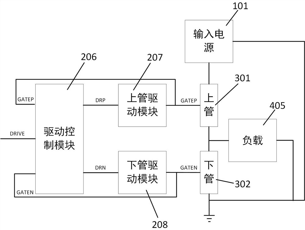
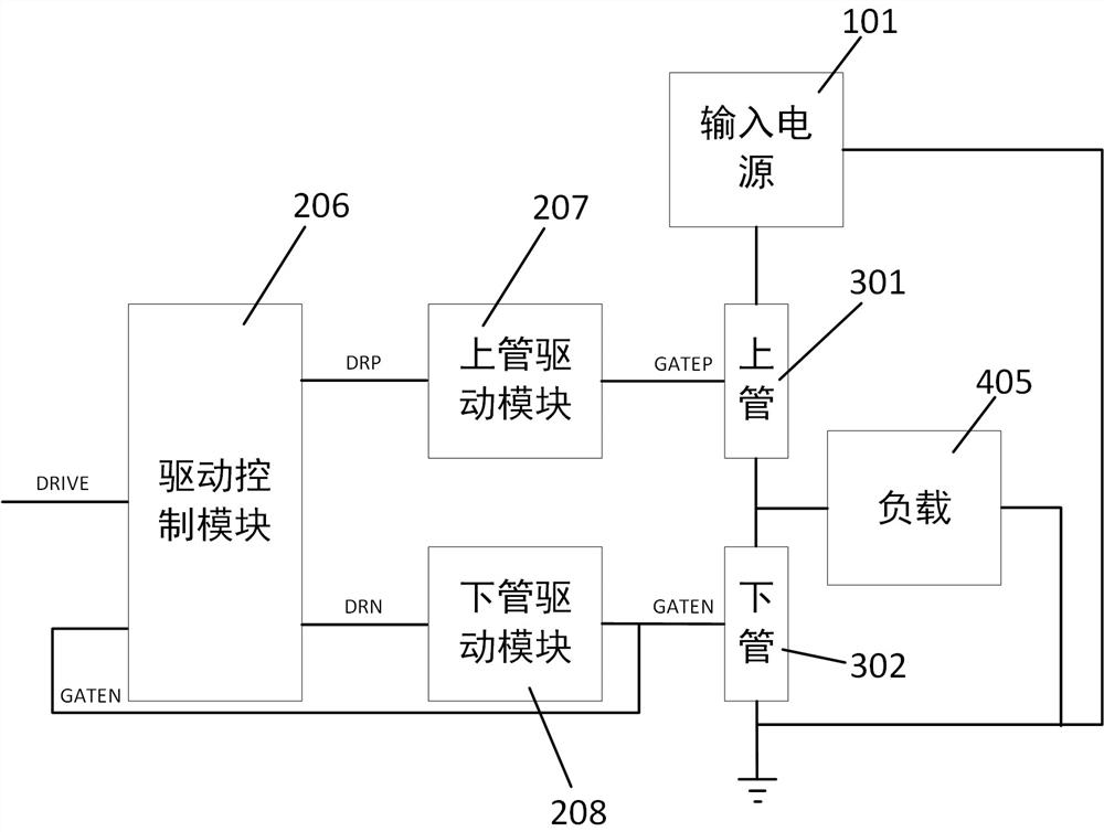
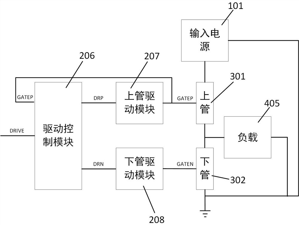
The invention provides a drive control module and a synchronous rectification circuit. Among them, the drive control module and the upper and lower tube drive modules work together. The upper and lower tubes driving module is used for outputting the driving voltage of the upper and lower tubes based on the output signal of the driving control module. The driving control module is configured to output the upper tube control signal and the lower tube control signal based on at least one of the rectified driving signal and the upper and lower tube driving voltages. This configuration cancels or partially cancels the fixed delay, and instead judges the opening and closing status of the upper and lower tubes through the control signal, and then outputs the control signal. On the other hand, it can also achieve shorter switching intervals under different working conditions, which improves the conversion efficiency of the system; it solves the need in the prior art to ensure that the upper tube and the lower tube will not be at the same time. A series of problems caused by the fixed delay set for opening.

Description

technical field [0001] The invention relates to the technical field of power chips, in particular to a drive control module and a synchronous rectification circuit. Background technique [0002] The BUCK type switching power supply system is divided into two working modes: synchronous rectification and asynchronous rectification. [0003] Among them, the asynchronous rectification system uses Schottky diodes as freewheeling tubes. Due to the existence of the voltage drop of the Schottky diodes, the system conversion efficiency is low. [0004] The synchronous rectification uses a MOS power tube as a freewheeling tube to improve the conversion efficiency of the system. Correspondingly, since the freewheeling tube is replaced by a Schottky diode with a MOS power tube, in order to avoid the system damage caused by the simultaneous opening of the upper and lower tubes of the synchronous rectification switching power supply system, The whole system needs to add a MOS driver modu...

Claims


Application Information

Patent Timeline
Patent Type & Authority Patents(China)
IPC IPC(8): H02M1/088H02M1/38H02M3/158
CPCH02M1/088H02M1/38H02M3/1588Y02B70/10
Inventor 李瑞平王建虎刘彬
Owner SHANGHAI XINLONG SEMICON TECH CO LTD
Learn More