
Angle-adjustable planing cutter

A planing knife and angle adjustment technology, applied in the field of medical devices, can solve problems such as waste, increase the economic burden of patients, etc., and achieve the effect of not easy to residue and controllable angle

Inactive Publication Date: 2022-06-07
THE FIRST AFFILIATED HOSPITAL OF WENZHOU MEDICAL UNIV
View PDF0 Cites 0 Cited by
  • Summary
  • Abstract
  • Description
  • Claims
  • Application Information

AI Technical Summary

Problems solved by technology

At present, the bendable planer head at home and abroad, once the outer knife tube is bent, the bending angle of the whole planer head is fixed, and in some surgical operations, due to the complexity of the natural passage of the human body, it is often necessary for one operation to Operations are performed at various angles, but since the bending angle of each planer head is fixed, one operation requires multiple curved planer heads with different bending angles, which increases the financial burden on patients and causes unnecessary waste

Method used


Image

  • Angle-adjustable planing cutter
  • Angle-adjustable planing cutter
  • Angle-adjustable planing cutter

Examples


Embodiment 1

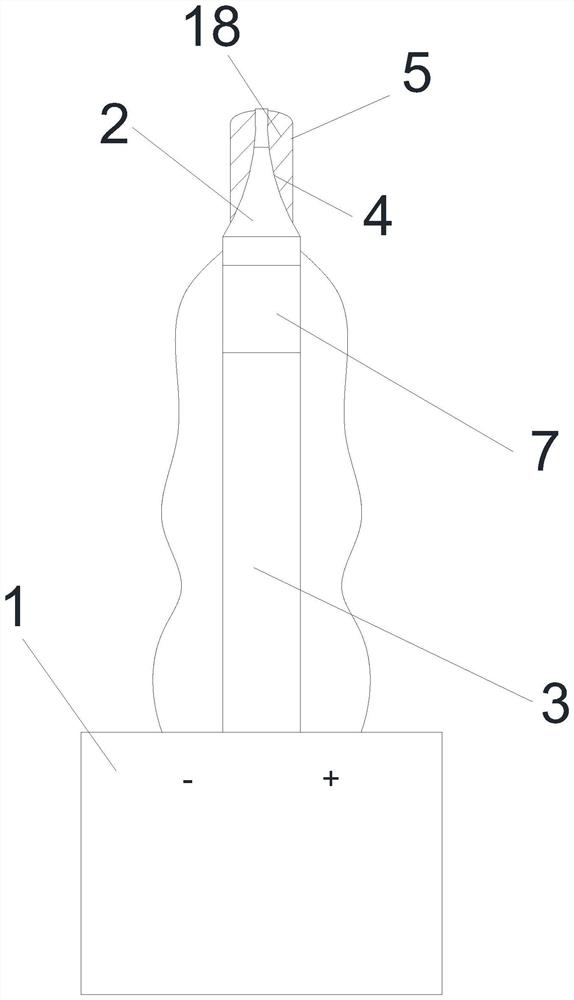
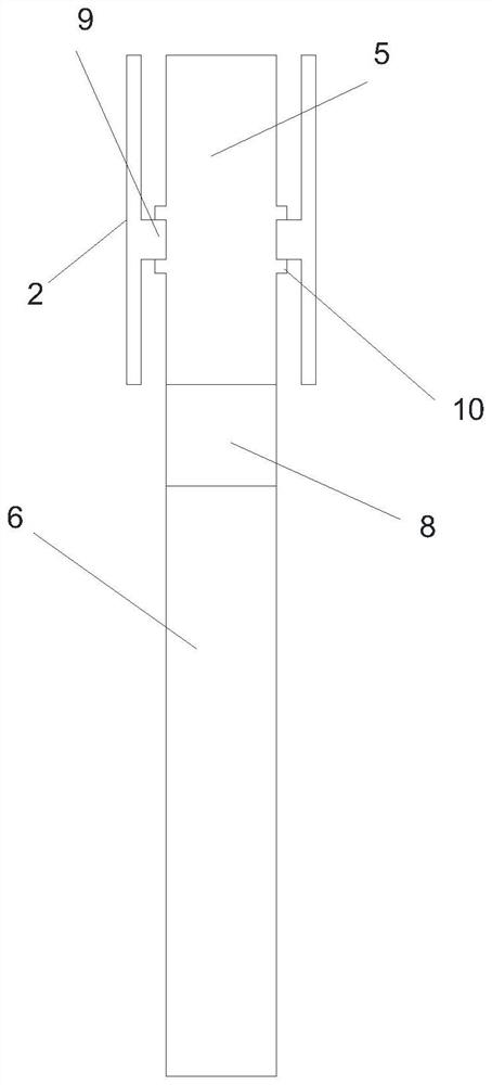
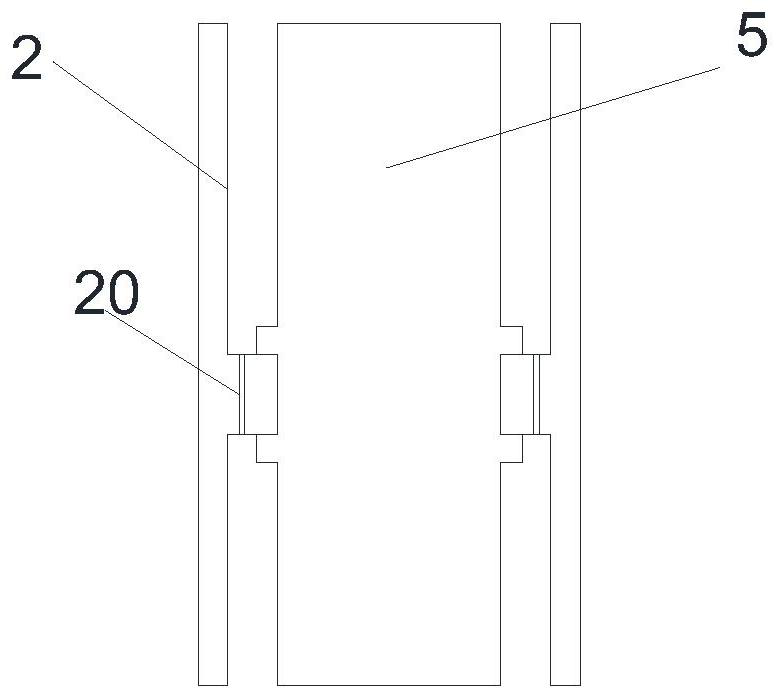
[0025] Example 1 combined with Figure 1-5 , an adjustable angle planing knife, comprising a main engine 1, an outer pipe, an inner knife pipe and a driving device, the main engine is provided with a driving device, the driving device is connected to the inner knife pipe and drives the inner knife pipe to rotate, and the outer side of the inner knife pipe is sleeved There is an outer tube, one end 3 of the outer tube is connected to the host, the end of the other end 2 of the outer tube is provided with an opening 4, the end of the inner knife tube is exposed at the other end of the outer tube, and there is a first section between one end of the outer tube and the other end of the outer tube. Telescopic bending section 7, one end 5 of the inner knife tube and the other end 6 of the inner knife tube are provided with a second telescopic bending section 8 that can transmit rotation, one end of the inner knife tube is provided with an end, one end of the inner knife tube The oute...


PUM


Abstract

A driving device is arranged in a main machine, the driving device is connected with an inner cutter pipe and drives the inner cutter pipe to rotate, the inner cutter pipe is sleeved with an outer pipe, one end of the outer pipe is connected with the main machine, an opening is formed in the tail end of the other end of the outer pipe, and the tail end of the inner cutter pipe is exposed out of the other end of the outer pipe. A first telescopic bent section is arranged between one end of the outer tube and the other end of the outer tube, a second telescopic bent section capable of transmitting rotation is arranged between one end of the inner knife tube and the other end of the inner knife tube, a tail end is arranged at one end of the inner knife tube, and an annular groove with the two side walls protruding is further formed in the outer side wall of one end of the inner knife tube. A protruding annular sliding block is arranged on the inner side wall of one end of the outer pipe, and the annular groove is clamped to the annular sliding block. The device has the advantages that bending can be conducted conveniently and rapidly, and the inner wall of an outer pipe cannot be polished; the structure is simple, and installation and cleaning are easy; and the bending angle is controllable, so that different angle requirements can be met conveniently.

Description

technical field [0001] The invention relates to the field of medical instruments, in particular to an angle-adjustable planer. Background technique [0002] A medical shaver is a surgical instrument used to shave biological bone tissue and / or soft tissue. The planing cutter head is composed of a rotatable inner cutter assembly and a fixed outer cutter assembly. During the process that the power mechanism drives the inner cutter assembly to rotate relative to the outer cutter assembly, the relative movement of the inner and outer cutter heads cuts the tissue; in order to adapt to complex The human body channel and the surgical angle, there is a planing head that can be bent. At present, for the bendable planing cutter head at home and abroad, once the outer cutter tube is bent and formed, the bending angle of the entire planing cutter head is fixed. However, in some surgical operations, due to the complexity of the natural passage of the human body, it is often necessary to ...

Claims


Application Information

Patent Timeline
Patent Type & Authority Applications(China)
IPC IPC(8): A61B17/32
CPCA61B17/32A61B2017/320008A61B2217/002A61B2217/005
Inventor 吴李闯刘彩龙叶奕亨苏陈显
Owner THE FIRST AFFILIATED HOSPITAL OF WENZHOU MEDICAL UNIV
Learn More