Magnetic type edge tool storage device
A storage device and magnetic suction technology, applied in the field of medical devices, can solve the problems of tipping sharp tool boxes, endangering the health of medical staff, and easily stabbing users' hands, etc., and achieve the effect of preventing tipping
- Summary
- Abstract
- Description
- Claims
- Application Information
AI Technical Summary
Problems solved by technology
Method used
Image

Examples
Embodiment 1
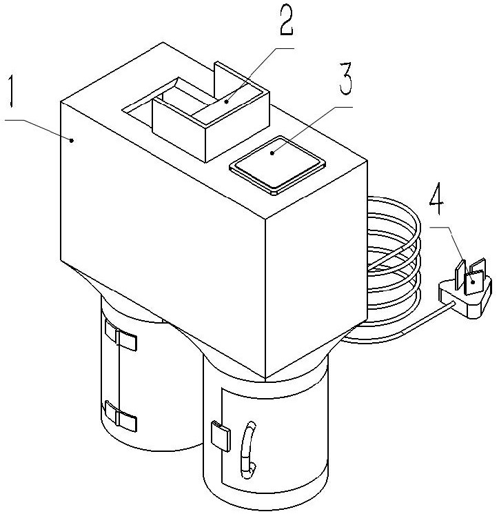
[0034] like Figure 1-3 As shown, a magnetic suction type sharp weapon storage device in this embodiment includes a support structure 2251, an execution device 2, a control structure 3 and a power supply structure 4; the execution device 2 is arranged inside the support structure 2251, and the execution device 2 and the support The structure 2251 is fixedly connected; the control structure 3 is arranged on the top of the support structure 2251, and the control structure 3 is fixedly connected with the support structure 2251; the power supply structure 4 is arranged on the outer side wall of the support structure 2251, and the power supply structure 4 is fixedly connected with the support structure 2251; A pressure sensor 5 for weight measurement is arranged inside the structure 2251; the execution device 2, the control structure 3, the pressure sensor 5 and the power supply structure 4 are connected to each other by wires; The execution device 2 separates the needle from the s...
Embodiment 2
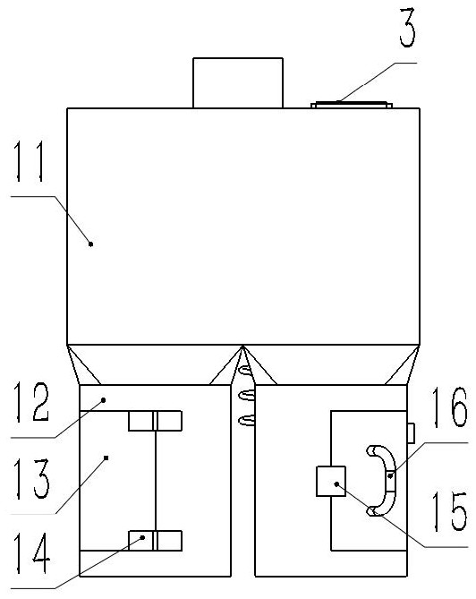
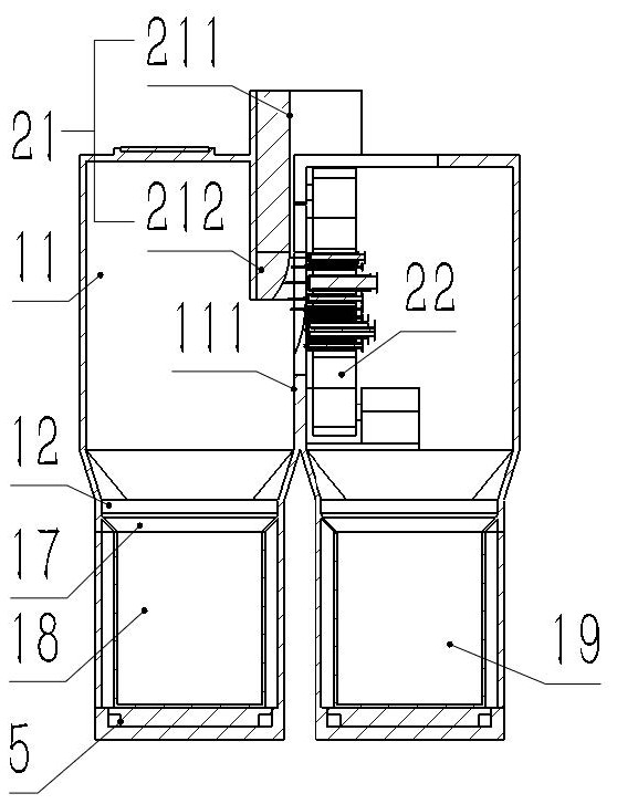
[0038] like Figure 4-6 As shown, this embodiment adds the following technical features on the basis of Embodiment 1:
[0039] The execution device 2 includes a magnetic structure 21 , a transmission assembly 22 and an extractor 23 ; a partition plate 111 and a magnetic support 112 are arranged inside the top covering structure 11 , the partition plate 111 is fixedly connected to the top covering structure 11 , and the magnetic support 112 is connected to The top covering structure 11 is fixedly connected; the magnetic structure 21 is arranged inside the magnetic support 112; the transmission component 22 is arranged on the side wall of the partition plate 111, and the transmission component 22 is connected with the partition plate 111; the remover 23 is arranged in the partition Inside the plate 111 , the extractor 23 is fixedly connected to the partition plate 111 .
[0040] The transmission assembly 22 includes a supporting wheel 221, a rotating motor 222, a driving wheel ...
Embodiment 3
[0046] like Figure 7-10 As shown, this embodiment adds the following technical features on the basis of Embodiment 1:
[0047] The extractor 23 includes a guide bracket 231, a centering bracket 232 and an extraction bracket 233; the extractor 23 includes two sets of mutually symmetrical guide brackets 231; the extractor 23 includes two sets of mutually symmetrical centering brackets 232; the extractor 23 includes two sets of The mutually symmetrical removal brackets 233; the guide bracket 231 is arranged on the top of the centering bracket 232; the centering bracket 232 is arranged on the top of the removal bracket 233; After that, it is transported to the centering bracket 232 by the transmission assembly 22, and the centering bracket 232 cooperates with the magnetic structure 21 so that the syringes 9 to be separated can be stuck on the extractor 23; the syringes 9 to be separated are driven by the transmission assembly 22 to pass through After centering the bracket 232, t...
PUM
 Abstract
Description
Claims
Application Information
 - R&D
- Intellectual Property
- Life Sciences
- Materials
- Tech Scout
- Unparalleled Data Quality
- Higher Quality Content
- 60% Fewer Hallucinations
Browse by: Latest US Patents, China's latest patents, Technical Efficacy Thesaurus, Application Domain, Technology Topic, Popular Technical Reports.
© 2025 PatSnap. All rights reserved.Legal|Privacy policy|Modern Slavery Act Transparency Statement|Sitemap|About US| Contact US: help@patsnap.com