Material separation structure inside a municipal road cleaning and maintenance device

A municipal road and separation structure technology, which is applied in the direction of solid separation, road surface cleaning, and separation of solids from solids with airflow, etc. It can solve the problem of increased driving force, inability to separate debris, and recyclable resources that cannot be reused, etc. question

Active Publication Date: 2020-10-27
苏州科腾软件开发有限公司
View PDF5 Cites 0 Cited by
  • Summary
  • Abstract
  • Description
  • Claims
  • Application Information

AI Technical Summary

Problems solved by technology

[0005] The purpose of the present invention is to provide a material separation structure inside the municipal road cleaning and maintenance device to solve the problem that the existing municipal road cleaning and maintenance device can only clean all the sundries on the road into the storage compartment, and cannot clean the sundries. Carry out separation work, so that recyclable resources such as metals and other light paper pieces contained in sundries cannot be reused, resulting in waste of resources, which does not meet modern garbage classification standards; the existing municipal road cleaning and maintenance devices cannot be used for screening fans The position adjustment along the two slide bars cannot adjust the wind direction, so that the cross air flow between the side fan and the screening fan is inconsistent with the discharge direction of the conveying frame, so that when the material passes through the cross air flow, the material falls in disorder, which is inconvenient Collect and process materials; the existing municipal road cleaning and maintenance device cannot adjust the distance between the adjustment wheel and the discharge wheel, and cannot adjust the tightness of the discharge belt, which is prone to slippage of the discharge belt, resulting in material Accumulation; the existing municipal road cleaning and maintenance device cannot adjust the tension of the conveyor belt, so that the conveyor belt will not slack, and the conveyor belt is prone to overtightening, resulting in increased driving force, wear and tear of the conveyor belt, and reduced service life of the conveyor belt.

Method used


Image

  • Material separation structure inside a municipal road cleaning and maintenance device
  • Material separation structure inside a municipal road cleaning and maintenance device
  • Material separation structure inside a municipal road cleaning and maintenance device

Examples


Embodiment Construction

[0031] The technical solutions of the present invention will be clearly and completely described below in conjunction with the embodiments. Apparently, the described embodiments are only some of the embodiments of the present invention, not all of them. Based on the embodiments of the present invention, all other embodiments obtained by persons of ordinary skill in the art without creative efforts fall within the protection scope of the present invention.

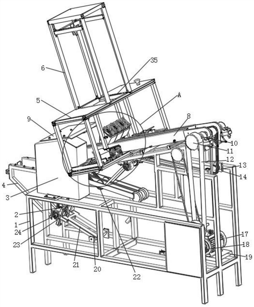
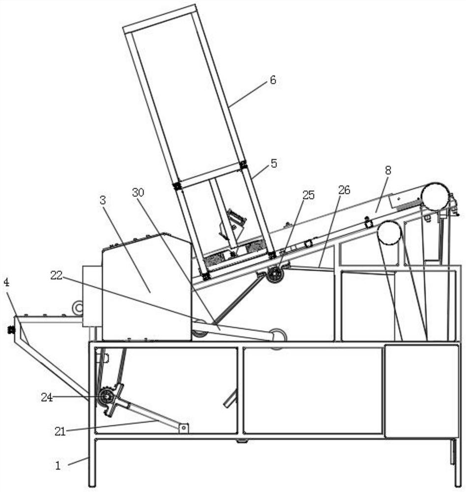
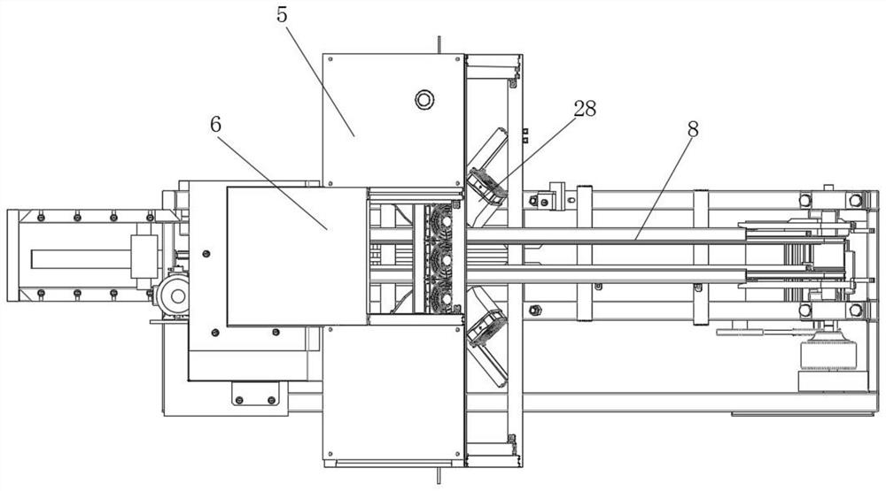
[0032] Such as Figure 1-6 As shown, a material separation structure inside a municipal road cleaning and maintenance device includes a mounting frame 1, a protective box 4 and a transmission frame 8. A fixed box 3 is provided at one end of the top of the mounting frame 1, and one side of the fixed box 3 is provided with There is a feeding plate 9, a first motor 16 is arranged below the feeding plate 9, two bearing seats 23 are arranged on the mounting frame 1 on one side of the first motor 16, and a discharge shaft is arra...


PUM


Abstract

The invention discloses a material separation structure inside a municipal road cleaning and maintenance device. The structure comprises a mounting frame, a protective box and a conveying frame, wherein a fixing box is arranged at one end of the top of the mounting frame, a feeding plate is arranged on one side of the fixing box, a first motor is arranged below the feeding plate, two bearing seatsare arranged on the position, on one side of the first motor, of mounting frame, a discharging shaft is arranged between the two bearing seats, a screw rod is driven to rotate through the output endof a third motor, when the screw rod is rotated, due to the fact that a nut seat is arranged on the screw rod and is in threaded connection with the screw rod, a screening fan moves up and down alongtwo sliding rods, the wind direction can be adjusted, so that the cross airflow between a side fan and the screening fan is consistent with the discharging direction of the conveying frame, when a material passes through the cross airflow, a material with the large mass falls onto a conveying belt, a material with the small mass is blown to a buffer ring through the airflow, and then fall on a discharging belt, so that the material separation work is realized, and the material is convenient to process.

Description

technical field [0001] The invention relates to the field of municipal road cleaning equipment, in particular to a material separation structure inside a municipal road cleaning and maintenance device. Background technique [0002] At present, most of the roads are cleaned manually by cleaners. There are a few municipal road cleaning and maintenance devices, most of which clean all the sundries on the road into the storage compartment and treat them as garbage. Do separation work. [0003] Chinese patent publication number CN101849805B discloses a separation device for separating particles from a fluid flow. In particular, but not exclusively, the invention relates to a vacuum cleaner having such a separating device for separating dust particles from a dust-laden airflow. The separation device comprises a first cyclonic cleaning stage, a second cyclonic cleaning stage arranged downstream of the first cyclonic cleaning stage, and an elongated filter arranged downstream of t...

Claims


Application Information

Patent Timeline
Patent Type & Authority Patents(China)
IPC IPC(8): B07B4/00B07B11/00B07B11/02B07B11/06E01H1/08
CPCB07B4/00B07B11/00B07B11/02B07B11/06E01H1/0836
Inventor 张德君
Owner 苏州科腾软件开发有限公司
Why Eureka
Try Eureka