Balloon catheter

A balloon catheter and balloon technology, applied in the field of medical devices, can solve the problems of increased organ necrosis, hemodynamic changes, and large overall profile of the balloon catheter, and achieve the effect of a small profile diameter

Pending Publication Date: 2022-06-07
LIFETECH SCIENTIFIC (SHENZHEN) CO LTD
View PDF9 Cites 0 Cited by
  • Summary
  • Abstract
  • Description
  • Claims
  • Application Information

AI Technical Summary

Problems solved by technology

However, the expansion of the balloon catheter of the prior art often blocks the blood supply, which may cause dramatic changes in hemodynamics, such as the blockage of blood flow causing severe defects in distal organs, increasing organ necrosis or exacerbating ischemia-reperfusion damage
In addition, the balloons in the prior art are sometimes used for first aid for closure of ruptured aneurysms, which can achieve rupture and bleeding of aneurysms with balloon closure, but the blockage of blood flow will cause severe ischemia and necrosis of distal organs
[0003] On the other hand, in the retraction process after the expansion of the balloon in the prior art, the balloon is irregular after the pressure is released, and the cross section of the balloon catheter is likely to form a two-lobed structure, and part of it is close to the surface of the catheter. The overall profile of the lower balloon catheter is too large, which can easily lead to damage to the vessel wall and displacement of the stent after implantation, which greatly affects the curative effect of the operation
At the same time, although the one-time use of medical devices significantly reduces the risk of infection, it also leads to an increase in the cost of patient treatment, and how to improve the multiple use rate of medical devices in the same patient treatment (for example, there are multiple lesion points, need to use the same balloon for dilation at different lesion points) will be an effective solution

Method used


Image

  • Balloon catheter
  • Balloon catheter
  • Balloon catheter

Examples


Embodiment Construction

[0031] In order to facilitate understanding of the present invention, the present invention will be described more fully hereinafter with reference to the related drawings. The preferred embodiments of the invention are shown in the accompanying drawings. However, the present invention may be embodied in many different forms and is not limited to the embodiments described herein. Rather, these embodiments are provided so that a thorough and complete understanding of the present disclosure is provided.

[0032] It should be noted that when an element is referred to as being "fixed to" another element, it can be directly on the other element or intervening elements may also be present. When an element is referred to as being "connected" to another element, it can be directly connected to the other element or intervening elements may also be present. The terms "inner", "outer", "left", "right" and similar expressions used herein are for the purpose of illustration only and do n...


PUM


Abstract

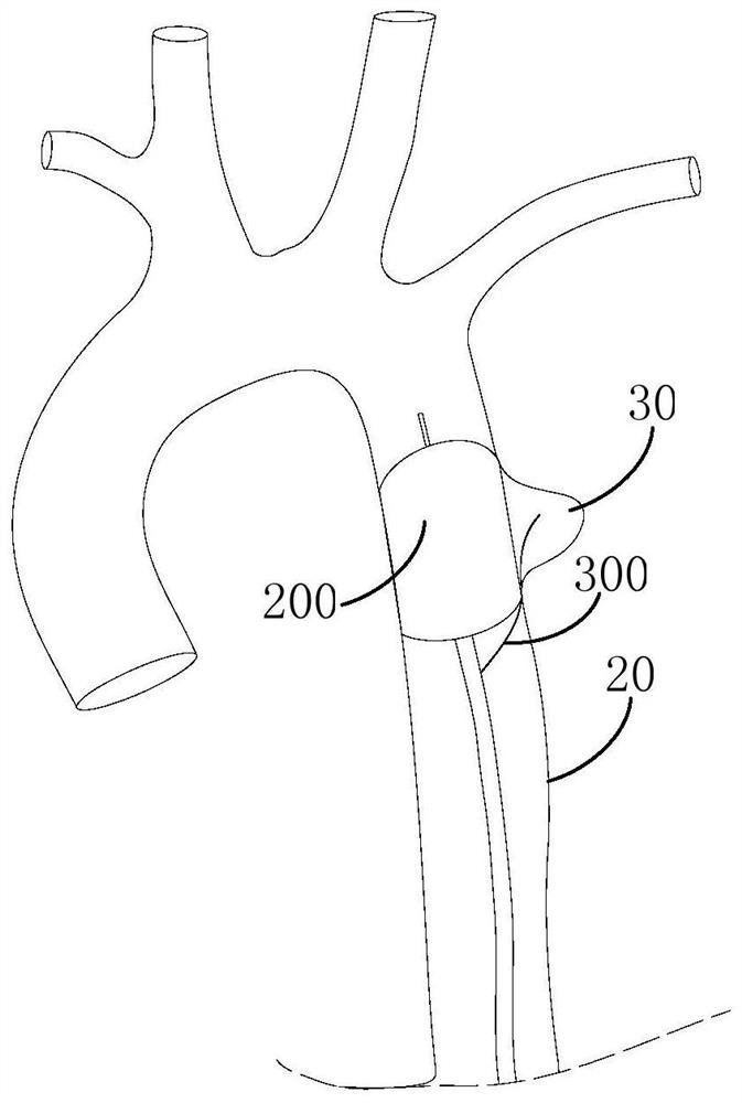
The invention relates to a balloon catheter which comprises a catheter assembly and a balloon, and the balloon is arranged at the far end of the catheter assembly. The balloon catheter further comprises a drainage tube, and the drainage tube is arranged on the outer surface of the balloon. When the balloon is full, blood can circulate at the two ends of the balloon through the drainage tube. Due to the arrangement of the drainage tube, after the balloon fills the blood vessel, blood can flow between the near end and the far end of the balloon through the drainage tube, and therefore the balloon is prevented from completely obstructing blood flow in the blood vessel. And on the basis of ensuring that the balloon expands the blood vessel or blocks the aneurysm, the blood can still circulate in the blood vessel.

Description

technical field [0001] The invention relates to the technical field of medical devices, in particular to a balloon catheter. Background technique [0002] Balloon catheters are widely used for dilation of intravascular stenotic lesions. However, the dilation of prior art balloon catheters often blocks blood supply, which may cause dramatic changes in hemodynamics, such as blockage of blood flow causing severe defects in distal organs, increasing organ necrosis or aggravating ischemia-reperfusion damage. In addition, the balloon of the prior art is sometimes used for emergency occlusion of aneurysm rupture, which can achieve the rupture and hemorrhage of aneurysm occlusion by the balloon, but the blockage of blood flow will cause severe ischemia and necrosis of distal organs. [0003] On the other hand, during the retraction process after the expansion of the balloon in the prior art, the pressure of the balloon is irregular after decompression, and the cross-section of the...

Claims


Application Information

Patent Timeline
Patent Type & Authority Applications(China)
IPC IPC(8): A61M25/10A61B17/12
CPCA61M25/1002A61B17/12113A61B17/12136A61B2017/12081
Inventor 张雄龙汉
Owner LIFETECH SCIENTIFIC (SHENZHEN) CO LTD
Why Eureka
Try Eureka