Supercharge Your Innovation With Domain-Expert AI Agents!

Radiointervention limb soft clamping limiter

A technology of limiter and soft clip, which is applied in the field of medical appliances, can solve the problems of secondary injury, drop, and image blur contrast of patients, and achieve the effects of improving success rate, ensuring accuracy, and avoiding secondary injury

Pending Publication Date: 2022-06-07
西安大兴医院
View PDF0 Cites 0 Cited by
  • Summary
  • Abstract
  • Description
  • Claims
  • Application Information

AI Technical Summary

Problems solved by technology

[0003] In clinical work, when the medical staff punctures the catheter and guide wire into the patient's limb, if the patient's limb moves or shakes unconsciously, the puncture will fail, and the medical staff needs to puncture again, causing secondary injury to the patient and also There will be motion artifacts in the DSA image, which will reduce the image blur and contrast, which is not conducive to the correct judgment of the target blood vessel by the operator, so that the patient cannot receive accurate treatment. In view of the above defects, it is necessary to design a soft clamping limit for radiological intervention Bit device

Method used


Image

  • Radiointervention limb soft clamping limiter
  • Radiointervention limb soft clamping limiter
  • Radiointervention limb soft clamping limiter

Examples


Embodiment 1

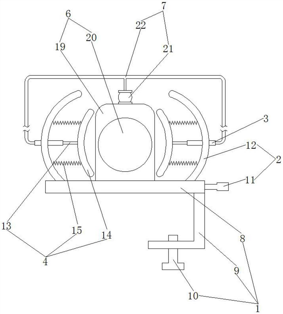
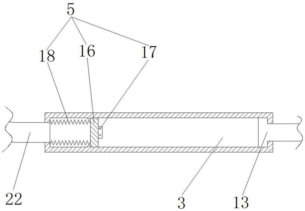
[0024] like figure 1 , figure 2 As shown in the figure, the radiological interventional limb soft clamping limiter includes a disassembly and assembly mechanism 1. The right side of the disassembly and assembly mechanism 1 rotates through a drive mechanism 2, and the left and right sides of the outside of the drive mechanism 2 are fixedly penetrated with an installation sleeve. 3. A clamping mechanism 4 is slidably arranged inside the mounting sleeve 3, a stabilizing mechanism 5 is slidably arranged inside the clamping mechanism 4, and a limiting mechanism 6 is fixed at the top rear end of the disassembly mechanism 1, so The top of the limiting mechanism 6 is fixedly provided with an exhaust mechanism 7 , and the other end of the exhaust mechanism 7 is fixed and penetrates through the outside of the mounting sleeve 3 .

[0025] For the radiological interventional limb soft clamping limiter, the medical staff first firmly connects the disassembly mechanism 1 with the bed edge...

Embodiment 2

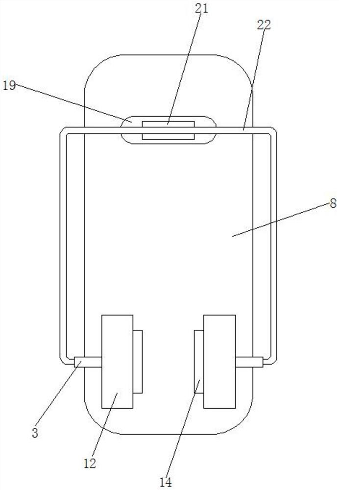
[0027] like figure 1 , figure 2 , image 3 As shown in the figure, the radiological interventional limb soft clamping limiter includes a disassembly and assembly mechanism 1. The right side of the disassembly and assembly mechanism 1 rotates through a drive mechanism 2, and the left and right sides of the outside of the drive mechanism 2 are fixedly penetrated with an installation sleeve. 3. A clamping mechanism 4 is slidably arranged inside the mounting sleeve 3, a stabilizing mechanism 5 is slidably arranged inside the clamping mechanism 4, and a limiting mechanism 6 is fixed at the top rear end of the disassembly mechanism 1, so The top of the limiting mechanism 6 is fixedly provided with an exhaust mechanism 7, and the other end of the exhaust mechanism 7 is fixed through the outside of the mounting sleeve 3. The disassembly mechanism 1 consists of a bottom plate 8, a clamping plate 9 and a stud 10. The bottom right side of the bottom plate 8 is fixed with a clamping pl...


PUM


Abstract

The invention discloses a radiation intervention limb soft clamping limiter which comprises a dismounting and mounting mechanism, a driving mechanism rotatably penetrates through the right side of the dismounting and mounting mechanism, mounting sleeves fixedly penetrate through the left side and the right side of the exterior of the driving mechanism, clamping mechanisms are slidably arranged in the mounting sleeves, and stabilizing mechanisms are slidably arranged in the clamping mechanisms. The rear end of the top of the dismounting and mounting mechanism is fixedly provided with a limiting mechanism, the top of the limiting mechanism is fixedly provided with an exhaust mechanism, and the other end of the exhaust mechanism fixedly penetrates through the outer side of the mounting sleeve. By means of the device, the success rate of puncture is increased, and secondary injury to a patient is avoided.

Description

technical field [0001] The invention relates to the technical field of medical appliances, in particular to a soft gripping limiter for radiological interventional limbs. Background technique [0002] The term Interventional Radiology was first coined by Margulis in 1967. It is a marginal subject that developed rapidly in the late 1970s. It is a series of technologies for the diagnosis and treatment of various diseases under the guidance of medical imaging equipment, based on imaging diagnostics and clinical diagnostics, combined with the principles of clinical therapeutics, using catheters, guide wires and other equipment. That is: under the guidance of imaging medicine (X-ray, ultrasound, CT, MRI), through percutaneous puncture or through the original orifice of the human body, a special catheter or instrument is inserted into the lesion for diagnostic angiography and treatment. Or tissue collection for cytological bacteriological and biochemical examinations. [0003] ...

Claims


Application Information

Patent Timeline
IPC IPC(8): A61N5/10
CPCA61N5/10A61N2005/1097
Inventor 陈国平
Owner 西安大兴医院
Features
  • R&D
  • Intellectual Property
  • Life Sciences
  • Materials
  • Tech Scout
  • Unparalleled Data Quality
  • Higher Quality Content
  • 60% Fewer Hallucinations
Learn More