Clamping device for automatic automobile production line

An automatic production line, clamping device technology, applied in the direction of workpiece clamping device, cleaning method using gas flow, cleaning method and utensils, which can solve the problem that the clamping mechanism cannot be adjusted, the surface of the part is worn, and the auto parts that cannot be clamped Protection and other issues to achieve the effect of increasing the clamping effect

Active Publication Date: 2022-06-07
济南驷正机电设备有限公司
View PDF7 Cites 1 Cited by
  • Summary
  • Abstract
  • Description
  • Claims
  • Application Information

AI Technical Summary

Problems solved by technology

[0003] The purpose of the present invention is to solve the problem that the clamped auto parts cannot be protected in the prior art, resulting in the uneven anti-slip lines on the clamping plate that are easy to cause wear on the surface of the parts, and the existing clamping mechanism cannot be used according to the size of the parts. The flaws of adjusting it, while the proposed clamping device for automotive automated production lines

Method used


Image

  • Clamping device for automatic automobile production line
  • Clamping device for automatic automobile production line
  • Clamping device for automatic automobile production line

Examples


Embodiment 1

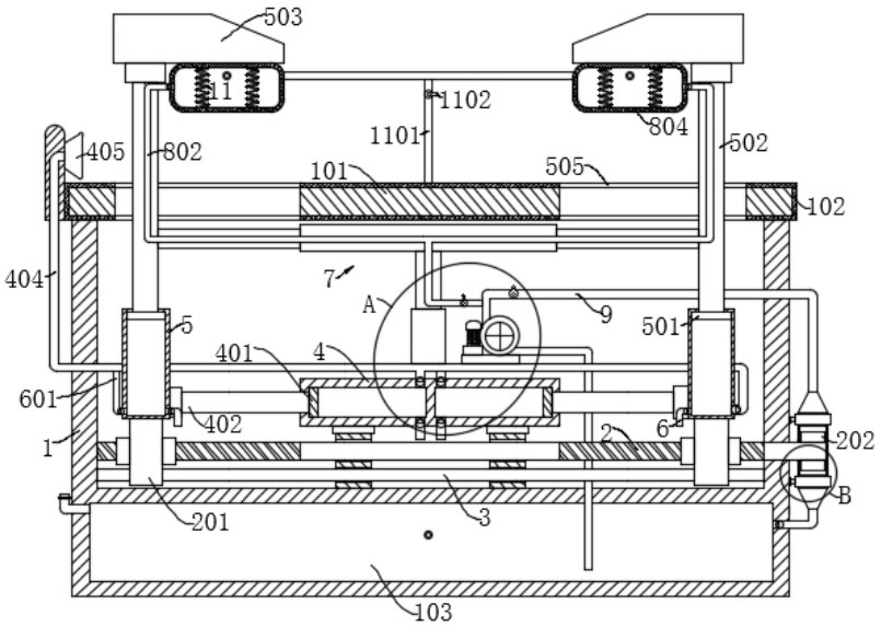
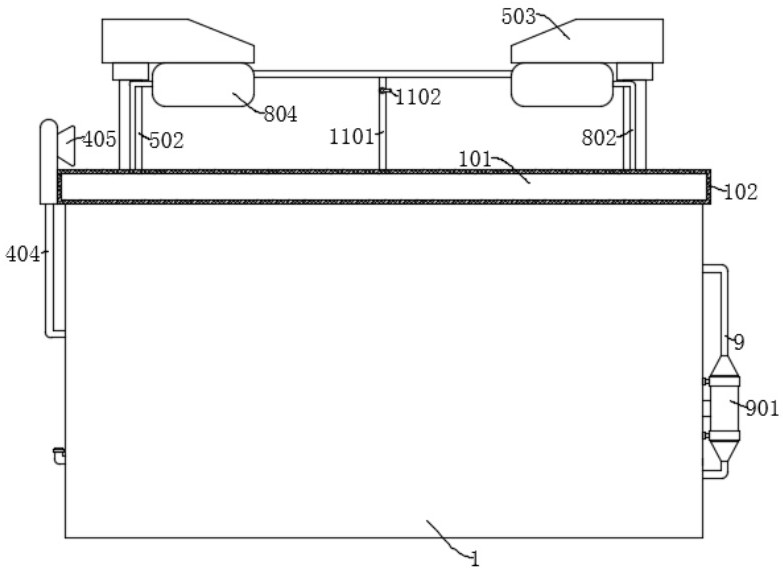
[0026] Example 1: Reference Figure 1-6, for the clamping device of the automotive automated production line, including housing 1, housing 1 top fixed connection to the support plate 101, housing 1 is provided with a water storage chamber 103, further comprising: symmetrically set with two sets of connectors 201, two sets of connectors 201 are set in the housing 1; Sleeve two 5, fixed mounted on two sets of connecting seats 201; Sleeve one 4, fixed mounted on the inner wall of the bottom of housing 1; Piston disc one 401, sliding connection in sleeve one 4, and piston disk one 401 and sleeve two 5 outer wall through the guide rod one 402 fixed connection; Nozzle 405, fixed to the support plate 101; Catheter one 403, one end of which is connected to the sleeve one 4; Catheter II 404, one end of which is connected to the sleeve one 4, the other end is connected to the nozzle 405; Piston disc II 501, sliding connection within sleeve II 5; Pipe one 6, connected to the sleeve two 5, sle...

Embodiment 2

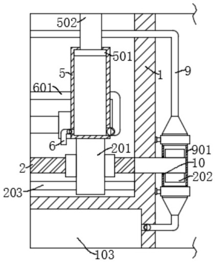
[0032] Example 2: Reference Figure 1 、 Figure 3 、 Figure 4 、 Figure 5 and Figure 6 , the clamping device for the automotive automated production line, substantially the same as Example 1, further is the drive component comprises a reciprocating screw 2, the reciprocating screw 2 rotation is connected to the inner wall of the housing 1, and the reciprocating screw 2 runs through the outer wall of one end of the supercharged tube 901 is fixedly connected to the impeller 202, the connector 201 is connected to the reciprocating screw 2 thread connection, the housing 1 is provided for the limiting limit of the connecting seat 201, the connecting seat 201 slides connected to the limit component.

[0033] Limiting components include a guide support rod 3, the guide support rod 3 is fixedly connected to the inner wall of the housing 1, the connecting seat 201 slides connected to the guide support rod 3.

[0034] The support plate 101 is opened with a chute 505, the connecting rod 502 slid...

Embodiment 3

[0038] Example 3: Reference Figure 1 、 Figure 3 and Figure 6 , the clamping device for the automotive automated production line, and Example 1 is basically the same, further, the pressurized tube 901 is provided with a sealing ring 10, the sealing ring 10 is fitted to the outer wall of the reciprocating screw 2; When the water flow impact impeller 202 through the booster pipe 901 drives the reciprocating screw 2 to rotate, the outer wall of the sealing ring 10 reciprocating screw 2 provided on the pressurized pipe 901 is attached, which can increase the sealing of the pressurized pipe 901, thereby effectively preventing the leakage of water through the pressurized pipe 901.


PUM


Abstract

The invention discloses a clamping device for an automatic automobile production line, and belongs to the technical field of clamping devices. The clamping device for the automatic automobile production line comprises a shell, a supporting plate is fixedly connected to the top of the shell, a water storage cavity is formed in the shell, and the clamping device further comprises two sets of connecting bases symmetrically arranged and arranged in the shell; according to the automobile part clamping device, when an automobile part is clamped, particulate matter impurities on the surface of the supporting plate can be cleaned, and the situation that the particulate matter impurities on the surface of the supporting plate abrade the automobile part in the clamping process is avoided; the air bag is expanded to abut against the automobile part, the clamping effect of the clamping plate on the automobile part is further improved, and due to the fact that the air bag has the elastic effect, the clamping effect of the clamping plate on the automobile part can be improved, and meanwhile the clamping plate is prevented from abrading the automobile part; and the distance between the two sets of clamping plates can be conveniently adjusted according to the sizes of the automobile parts.

Description

Technical field [0001] The present invention relates to the technical field of the clamping device, in particular to the clamping device for automotive automated production lines. Background [0002] With the continuous progress of modern manufacturing technology, the production of automobiles widely adopts assembly line production methods, which can effectively improve the production efficiency and quality of automobiles, and at the same time require the use of various types of clamping devices, however, the current existing clamping devices, when clamping auto parts, due to the inability to protect the clamped auto parts, resulting in uneven anti-slip lines on the clamping plate is easy to cause wear on the surface of the parts, and the existing clamping mechanism can not be adjusted according to the size of the parts. Contents of the Invention [0003] Object of the present invention is to solve the prior art can not be clamped auto parts for protection, resulting in uneven a...

Claims


Application Information

Patent Timeline
Patent Type & Authority Applications(China)
IPC IPC(8): B25B11/00B08B5/02
CPCB25B11/00B08B5/02Y02A20/108
Inventor 韩乃朴唐浩高栋
Owner 济南驷正机电设备有限公司
Why Eureka
Try Eureka