High-efficiency injection molding machine
An injection molding machine, high-efficiency technology, applied in the field of injection molding, can solve problems such as difficult demoulding, demoulding residue, inaccurate molding, etc., to achieve the effect of reducing grinding, reducing contact area, and precise molding
- Summary
- Abstract
- Description
- Claims
- Application Information
AI Technical Summary
Problems solved by technology
Method used
Image
Examples
Embodiment 1
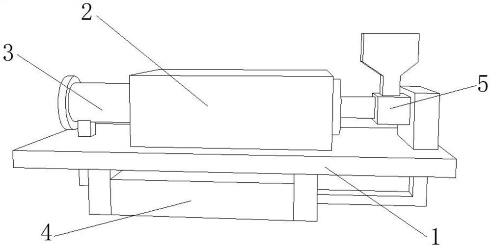
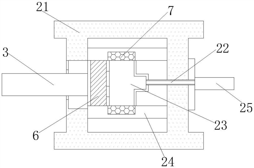
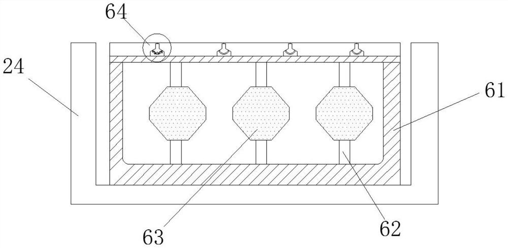
[0026] like Figure 1-3 As shown, the present invention provides a technical solution: a high-efficiency injection molding machine, comprising an operation table 1, an injection mechanism 2 is fixedly connected to the upper surface of the operation table 1, and the injection mechanism 2 includes a processing box shell 21, The bottom of the processing box shell 21 is fixedly connected to the upper surface of the operating table 1, the lower surface of the operating table 1 is fixedly connected with a motor box 4, and the outer surface of the processing box shell 21 is slidably connected with a push rod 3 , the outer surface of the push rod 3 penetrates the processing box shell 21 and extends to the inner cavity, and the end of the processing box shell 21 away from the push rod 3 is fixedly connected with a melting box 25 , and the outer surface of the melting box 25 is fixed The raw material barrel 5 is connected, the output end of the melting box 25 is fixedly connected with a...
Embodiment 2
[0031] like Figure 4 As shown, on the basis of the first embodiment, the present invention provides a technical solution: a second ring 644 is fixedly connected to the top of the airbag 61, and the second ring 644 is connected to the first ring through an elastic bending rod 642. Ring 641 active connection.
[0032] The second embodiment has the following working steps:
[0033] Step 1. When the cooling system is activated, the first ring 641 is first separated from the plastic. When the plastic is cooled to the middle, the second ring 644 is separated from the plastic. The first ring 641 and the second ring 644 are separated. It cooperates to achieve layer-by-layer shedding and separation, to achieve the effect of gradually reducing the contact area between the airbag and the plastic, improve the separation efficiency, make the plastic model easier to separate, reduce the plastic adhesion on the outer surfaces of the first ring 641 and the second ring 644, save money resou...
Embodiment 3
[0035] like Figure 5As shown, on the basis of Embodiment 1 and Embodiment 2, the present invention provides a technical solution: a cooling column 24 is fixedly connected to the inner wall of the processing box shell 21, and a cooling column 24 is fixedly connected to the outer surface of the cooling column 24. Condensing mechanism 7, the condensing mechanism 7 includes a cooling groove 75, the cooling groove 75 is fixedly connected to the outer surface of the cooling column 24, and the inner wall of the cooling groove 75 is fixedly connected with a cold runner 71, the cold runner 71 Passing through the cooling tank 75 and extending to the inner cavity, the bottom end of the cold runner 71 is fixedly connected with a condensation pipe 72, and the outer surface of the condensation pipe 72 is fixedly connected with an elastic extension rod 73, and the bottom of the elastic extension rod 73 is fixedly connected A magnetic layer 74 is fixedly connected, and an elastic metal strip...
PUM
 Abstract
Description
Claims
Application Information
 - R&D
- Intellectual Property
- Life Sciences
- Materials
- Tech Scout
- Unparalleled Data Quality
- Higher Quality Content
- 60% Fewer Hallucinations
Browse by: Latest US Patents, China's latest patents, Technical Efficacy Thesaurus, Application Domain, Technology Topic, Popular Technical Reports.
© 2025 PatSnap. All rights reserved.Legal|Privacy policy|Modern Slavery Act Transparency Statement|Sitemap|About US| Contact US: help@patsnap.com


