Cooling system of shaft system of wind generating set and wind generating set
A technology for wind turbines and cooling systems, applied in wind turbines, wind power generation, engines, etc., can solve the problems of single method, failure of cooling devices, low cooling efficiency, etc., and achieve the effect of low temperature and effective heat dissipation
- Summary
- Abstract
- Description
- Claims
- Application Information
AI Technical Summary
Problems solved by technology
Method used
Image

Examples
Embodiment 1
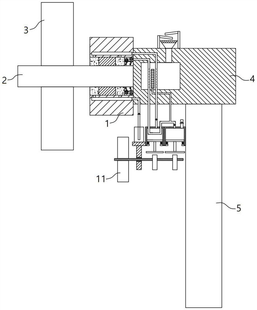
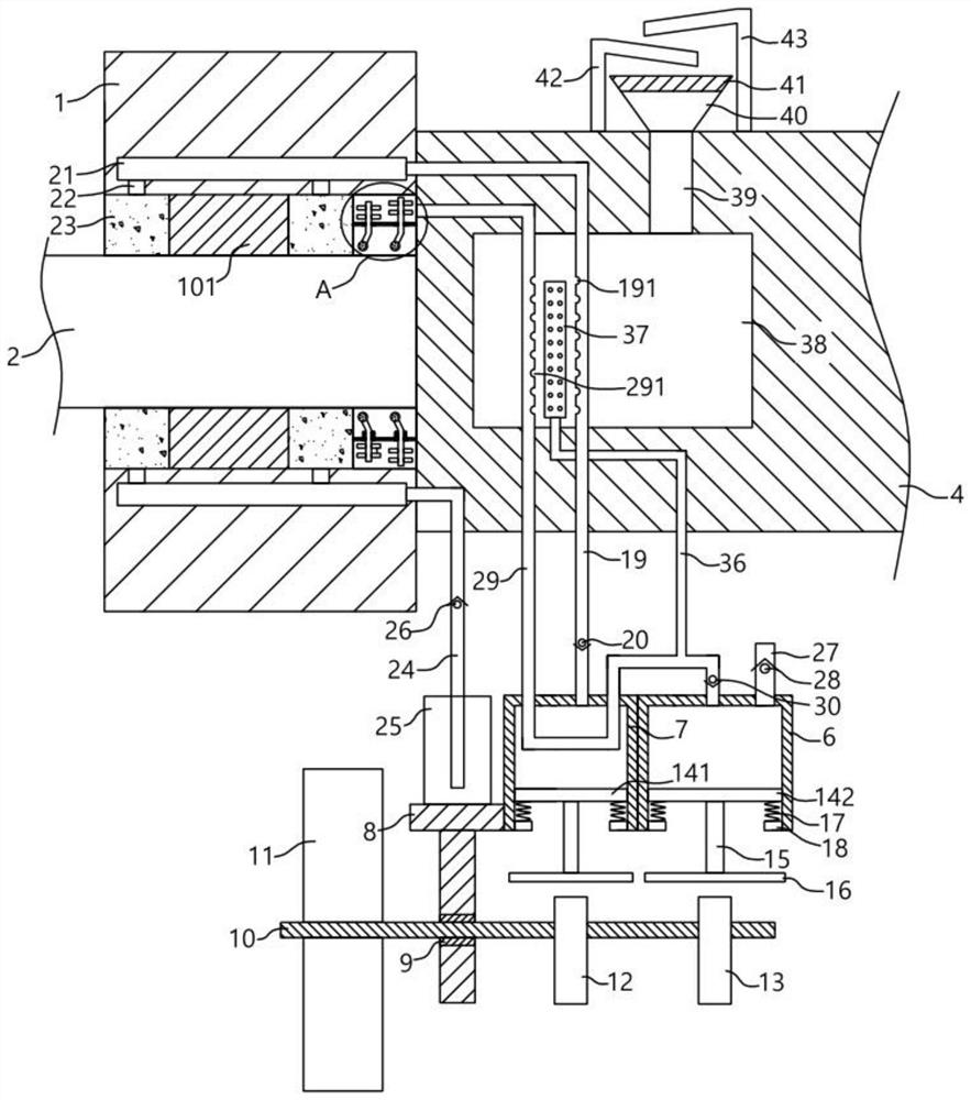
[0029] A cooling system for a shaft system of a wind turbine, comprising a generator subsystem 1, a main bearing 101 is arranged in the generator subsystem 1, and a central rotating shaft 2 is arranged in the main bearing 101, so the central rotating shaft 2 can rotate, and the central rotating shaft 2 A plurality of fan blades 3 are fixedly arranged on the upper part, a nacelle 4 is arranged on the side of the generator subsystem 1 away from the fan blades 3, a tower frame 5 is fixedly arranged below the nacelle 4, and an air box 6 is fixedly arranged on the tower frame 5. 6 is used for transfer and pumping out gas, the side of the air box 6 is fixedly provided with a water tank 7, the water tank 7 stores cooling water, the side of the water tank 7 is fixedly provided with a support frame 8, and the support frame 8 is hingedly provided with a rotating rod 10. , the rotating rod 10 can be rotated in place, and the rotating rod 10 is fixedly provided with a transmission blade 11...
Embodiment 2
[0033] A cooling system for a shaft system of a wind turbine, comprising a generator subsystem 1, a main bearing 101 is arranged in the generator subsystem 1, a central rotating shaft 2 is arranged in the main bearing 101, and a plurality of fan blades are fixedly arranged on the central rotating shaft 2 3. A nacelle 4 is provided on the side of the generator subsystem 1 away from the fan blade 3, a tower 5 is fixedly arranged below the nacelle 4, and an air box 6 is fixed on the tower 5, and the air box 6 is used for transfer and pumping out gas , the side of the air box 6 is fixed with a water tank 7, the water tank 7 stores cooling water, the side of the water tank 7 is fixed with a support frame 8, the support frame 8 is T-shaped, and its longitudinal section is embedded with a first installation bearing. 9. The rotating rod 10 is arranged through the first installation bearing 9, and the first installation bearing 9 here plays a role of providing a stable rotation support ...
Embodiment 3
[0037] On the basis of the above-mentioned first and second embodiments, this embodiment adds the following structure: a push rod 15 is fixedly arranged below the first piston plate 141 and the second piston plate 142 , and the lower part of the push rod 15 is fixedly arranged There is a push plate 16, so when the push plate 16 is stressed, it can push the corresponding first piston plate 141 or the second piston plate 142 through the push rod 15. Both the lower ends of the first piston plate 141 and the second piston plate 142 are Symmetrical connection is provided with a spring 17, the spring 17 has good telescopic elasticity, the spring 17 is connected to the limit block 18, and the limit block 18 is correspondingly fixed on the inner walls of the air box 6 and the water tank 7, and is used for the first piston plate. 141. The movement range of the second piston plate 142 is limited to prevent it from being separated from the corresponding water tank 7 or air tank 6.
PUM
 Abstract
Description
Claims
Application Information
 - R&D
- Intellectual Property
- Life Sciences
- Materials
- Tech Scout
- Unparalleled Data Quality
- Higher Quality Content
- 60% Fewer Hallucinations
Browse by: Latest US Patents, China's latest patents, Technical Efficacy Thesaurus, Application Domain, Technology Topic, Popular Technical Reports.
© 2025 PatSnap. All rights reserved.Legal|Privacy policy|Modern Slavery Act Transparency Statement|Sitemap|About US| Contact US: help@patsnap.com