
Auxiliary equipment for anchor rod drawing experiment and experiment instrument

A kind of auxiliary equipment and experimental technology, which is applied in the direction of instruments, scientific instruments, and the use of stable tension/pressure to test the strength of materials, etc., can solve the problems of connection troubles and difficulties for researchers, and achieve the effect of simple structure and reasonable design

Inactive Publication Date: 2022-06-07
WUHAN INSTITUTE OF TECHNOLOGY
View PDF16 Cites 0 Cited by
  • Summary
  • Abstract
  • Description
  • Claims
  • Application Information

AI Technical Summary

Problems solved by technology

Using the on-site bolt puller requires the bolt to be made large enough, which consumes a lot of manpower, material and financial resources; using a tension machine to test the anchoring performance of the bolt is simple, efficient, and accurate. The only disadvantage is the upper and lower jaws of the tension machine The connection between the mouth and the anchor has always been a big problem for researchers.

Method used


Image

  • Auxiliary equipment for anchor rod drawing experiment and experiment instrument
  • Auxiliary equipment for anchor rod drawing experiment and experiment instrument
  • Auxiliary equipment for anchor rod drawing experiment and experiment instrument

Examples


Embodiment 1

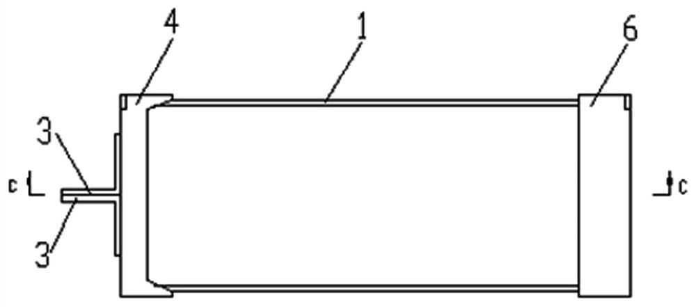
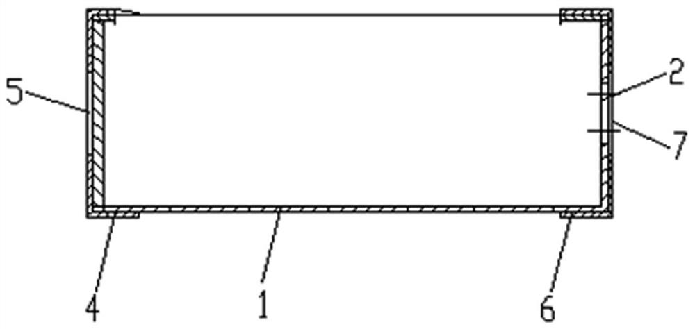
[0036] like Figure 1 to Figure 5 As shown, this embodiment provides an auxiliary equipment for an anchor rod pulling experiment, including a carrying box 1, one side of the carrying box 1 is open, one end of which is fixedly installed with a tensile member, and the other end is provided with a through-hole penetrating through the inside and outside. hole 2.

[0037] During the experiment, manually put the anchor rod 11 to be pulled into the carrying box 1, so that the steel bar at one end of the anchor rod 11 passes through the through hole 2, which is convenient to quickly fix the anchor rod 11, so that the pull test instrument can perform the pull test.

[0038] Preferably, in this embodiment, the carrier box 1 is preferably a rectangular box body with a regular shape.

[0039] This embodiment is simple in structure and reasonable in design, and can realize the fast clamping of the anchor rod 11, so as to quickly complete the pull-out experiment of the anchor rod 11, so as...

Embodiment 2

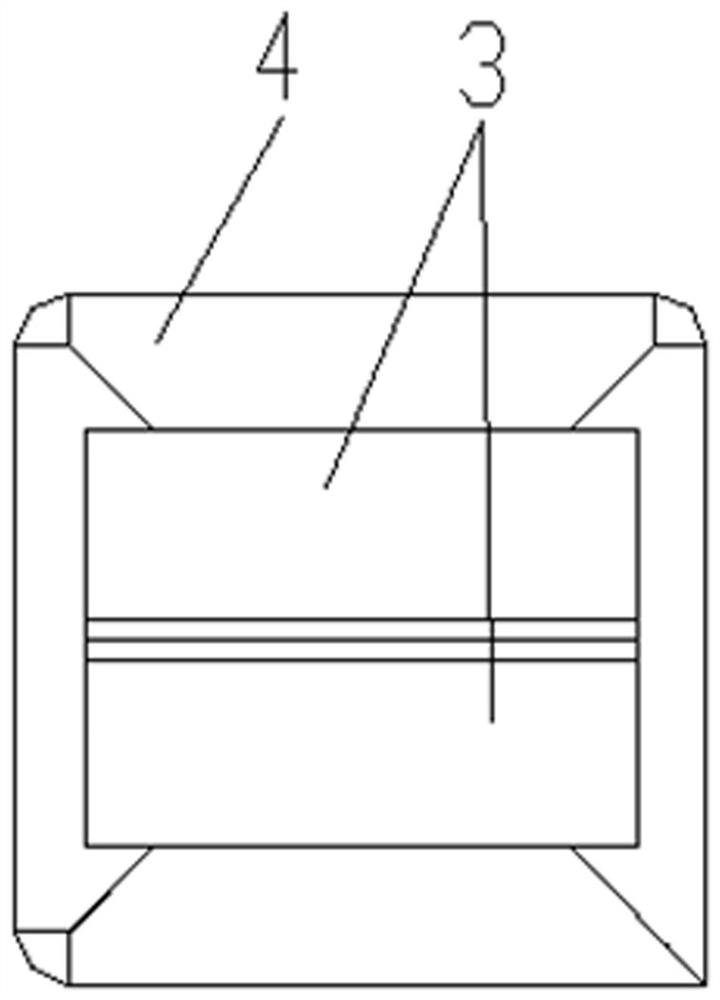
[0041] On the basis of Embodiment 1, in this embodiment, the tension member includes at least one tension plate 3 , and the tension plate 3 is fixedly installed at one end of the carrying box 1 .

[0042] The solution is simple in structure and reasonable in design. During the experiment, the fixing pliers of the pull-out tester can clamp the bearing plate 3 to complete the fast fixing of the anchor rod 11 so as to complete the pull-out test of the anchor rod 11 .

[0043] In addition to the above-mentioned embodiments, the above-mentioned tensile member may also be a tensile rod or a tensile block.

Embodiment 3

[0045] On the basis of Embodiment 2, in this embodiment, the tension member includes two tension plates 3, one end of the two tension plates 3 is fixedly connected to one end of the carrying box 1 respectively, and the other ends are close to each other.

[0046] The structure is simple, the design is reasonable, the bearing capacity of the tension member is enhanced, the service life thereof is prolonged, and the cost is reduced.

[0047] In addition to the above-mentioned embodiments, the tensile plate 3 can also be a flat plate, which is arranged perpendicular to one end of the carrying box 1 , and one end of which is fixedly connected to one end of the carrying box 1 .


PUM


Abstract

The auxiliary equipment comprises a bearing box, one side of the bearing box is open, one end of the bearing box is fixedly provided with a tension bearing piece, and the other end of the bearing box is provided with a through hole penetrating through the inside and the outside. The device has the beneficial effects that the structure is simple, the design is reasonable, and the anchor rod can be quickly clamped, so that a drawing experiment of the anchor rod is quickly completed, the performance of the anchor rod is well detected, and the problem that the anchor rod cannot be combined with a tensile machine during an indoor experiment is effectively solved.

Description

technical field [0001] The invention relates to the technical field of drawing equipment, in particular to an auxiliary equipment and an experimental instrument for an anchor rod drawing experiment. Background technique [0002] The bolt pulling tester is mainly used to detect the anchoring force of various bolts, steel bars and other bolts. The bolt puller is composed of a manual pump, a hydraulic cylinder, an intelligent digital pressure gauge, a high-pressure oil pipe with a quick connector, an anchor and a portable carrying case. [0003] Most of the bolt pullers seen and used in the market are used for on-site bolt detection. When the bolt is detected, the bolt has been anchored in the rock mass and a certain length is reserved. In the indoor bolt pull-out detection, concrete is often used to simulate the rock mass, and the bolt is embedded in the concrete to form the bolt. Using the on-site bolt puller needs to make the bolt large enough, which consumes a lot of manp...

Claims


Application Information

Patent Timeline
Patent Type & Authority Applications(China)
IPC IPC(8): G01N3/08G01N3/02
CPCG01N3/08G01N3/02G01N2203/0003G01N2203/0017G01N2203/005G01N2203/0266G01N2203/0676G01N2203/0682Y02E30/30
Inventor 陈清运曾顺洪董宏涛魏敬芮张海建唐斌向柳
Owner WUHAN INSTITUTE OF TECHNOLOGY
Learn More