
Ship target interference detection method based on satellite-borne Ka-band SAR (Synthetic Aperture Radar) system

A ka-band and target technology, which is applied in the field of ship target interference detection, can solve the problems of large loss of millimeter-wave SAR systems and greater power gain requirements, and achieve the goals of improving detection and recognition performance, suppressing energy, and improving signal-to-noise ratio Effect

Active Publication Date: 2022-06-07
BEIJING SATELLITE INFORMATION ENG RES INST
View PDF11 Cites 4 Cited by
  • Summary
  • Abstract
  • Description
  • Claims
  • Application Information

AI Technical Summary

Problems solved by technology

[0004] Patent CN106908793A discloses a Ka-band along-track interferometric SAR system and its working method. The Ka-band along-track interferometric SAR system includes: a transmitting antenna mounted on a satellite and first receiving antennas respectively located on both sides of the transmitting antenna on the same star , The second receiving antenna, the distance receiving antenna adopts multiple apertures to separately receive pulse signal echoes, and uses DBF-SCORE technology to synthesize high-gain narrow beams to realize the reception of echoes, which solves the problem of Ka-band millimeter-wave SAR systems The problem of large loss in atmospheric propagation and greater demand for system power gain, to achieve small-scale high-precision ocean current velocity measurement, but does not involve the above-mentioned problems

Method used


Image

  • Ship target interference detection method based on satellite-borne Ka-band SAR (Synthetic Aperture Radar) system
  • Ship target interference detection method based on satellite-borne Ka-band SAR (Synthetic Aperture Radar) system
  • Ship target interference detection method based on satellite-borne Ka-band SAR (Synthetic Aperture Radar) system

Examples


Embodiment Construction

[0040] In order to more clearly describe the embodiments of the present invention or the technical solutions in the prior art, the accompanying drawings required in the embodiments will be briefly introduced below. Obviously, the drawings in the following description are only some embodiments of the present invention, and for those of ordinary skill in the art, other drawings can also be obtained from these drawings without creative efforts.

[0041]The present invention will be described in detail below with reference to the accompanying drawings and specific embodiments. The embodiments cannot be repeated here, but the embodiments of the present invention are not limited to the following embodiments.

[0042] In the following exemplary embodiments of the present invention, a method for detection of ship target interference based on the spaceborne Ka-band SAR system is described.

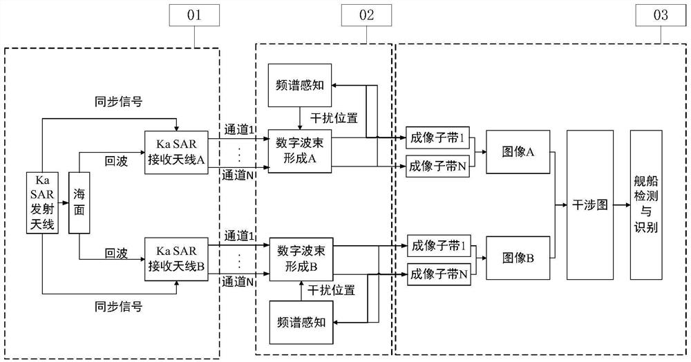
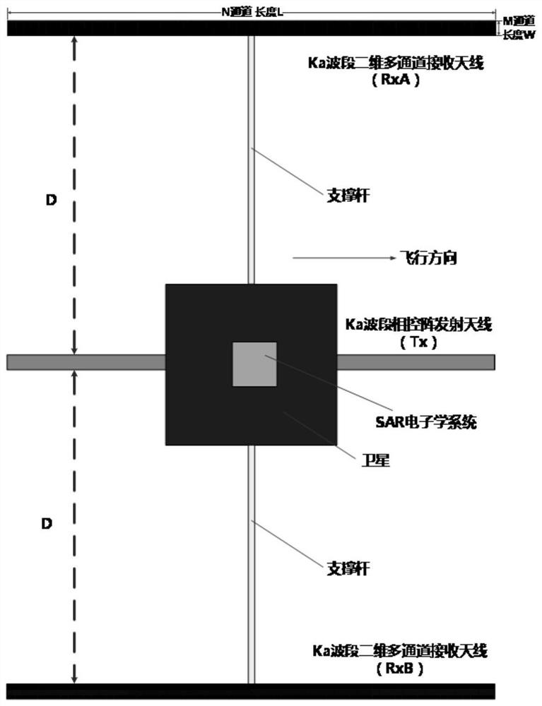
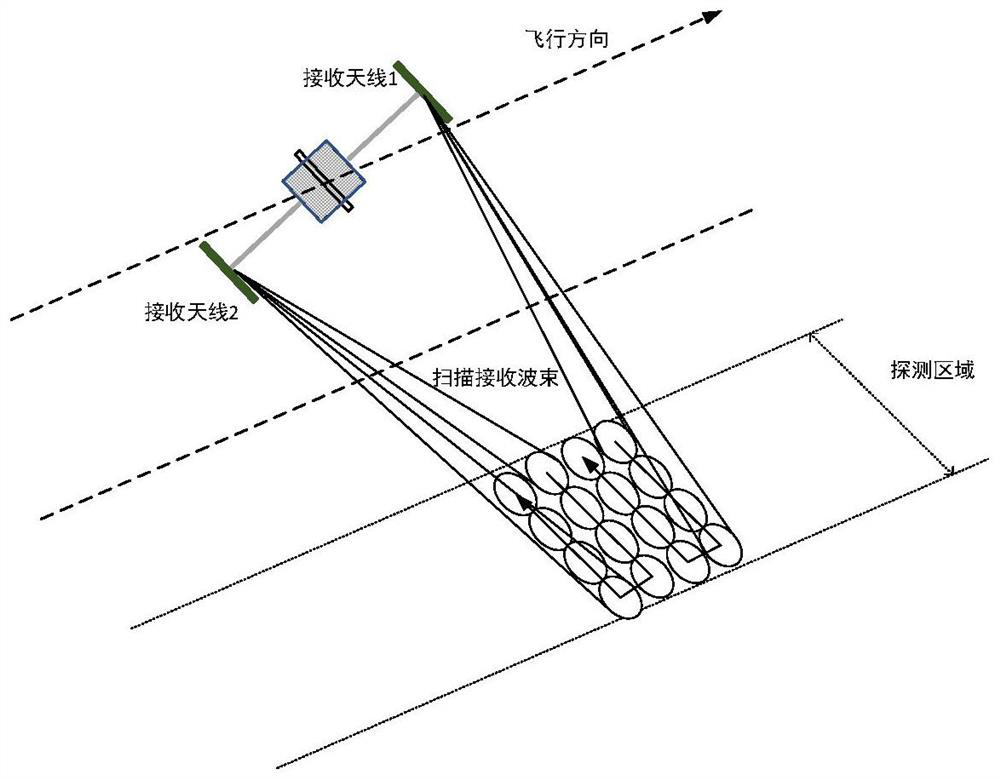
[0043] like figure 1 The overall architecture of the three-antenna spaceborne Ka-band SAR syst...


PUM


Abstract

The invention relates to a ship target interference detection method based on a satellite-borne Ka-band SAR (Synthetic Aperture Radar) system, which comprises the following steps of: scanning orthogonal signals of a pulse repetition period in an imaging area by using a Ka-band transmitting antenna to realize coverage of large width and large Doppler bandwidth; before pulse emission, a Ka wave band receiving antenna is used for carrying out parallel receiving and digital beam forming recovery on echo signals with large breadth and large Doppler bandwidth, and direction sources of interference signals are obtained; receiving data of a Ka-band receiving antenna is subjected to weighting processing to control a direction function, a nulling technology is used in the direction of an interference signal, the interference signal is suppressed, and interference caused by a sidelobe strong target of the Ka-band receiving antenna is suppressed at the same time; and obtaining an interference SAR image of the imaging area by using the Ka-band SAR cross-rail baseline, extracting elevation winding distribution information, and detecting and identifying the ship target according to the elevation winding distribution characteristics of the ship target. The ship target detection and recognition performance can be improved.

Description

technical field [0001] The invention relates to the technical field of target detection, in particular to a ship target interference detection method based on a spaceborne Ka-band SAR system. Background technique [0002] Compared with low-band SAR, spaceborne Ka-band SAR has strong ability to characterize target details and high resolution. Except for high-intensity rainfall, it is close to all-day and all-weather detection. At the same time, Ka-band SAR has weak penetrating ability, which can better reflect the real surface height and obtain high-precision imaging target height information. Due to the short wavelength, the spaceborne Ka-band SAR inter-orbit interference baseline can obtain the same elevation accuracy as the existing conventional spaceborne SAR at more than ten meters, and can realize the elevation measurement of single satellite and single flight. Airborne SAR systems from Ka-band to W-band have been developed internationally. With the theoretical key tec...

Claims


Application Information

Patent Timeline
IPC IPC(8): G01S13/90
CPCG01S13/9004G01S13/9021
Inventor 张涛夏正欢赵志龙刘新张瑶张闯高文宁张庆君易春宏梁银川金世超岳富占
Owner BEIJING SATELLITE INFORMATION ENG RES INST
Learn More