
Four-shaft shredding machine for waste steel

A shredder and steel technology, applied in the direction of grain processing, etc., to achieve the effect of enhanced secondary shredding effect, enhanced extrusion force, and improved shredding effect

Active Publication Date: 2022-06-10
唐山谷润科技有限公司
View PDF11 Cites 0 Cited by
  • Summary
  • Abstract
  • Description
  • Claims
  • Application Information

AI Technical Summary

Problems solved by technology

[0004] There are still some problems in the existing four-shaft shredder. The crushing of scrap steel comes from the extrusion and tearing of the blade, and the extrusion and tearing of the blade comes from The four-axis torque, this single power source crushes the scrap steel slowly, and the scrap steel falling on the sieve plate, because the blade cannot completely throw it away, makes the scrap steel easy to accumulate, which is As a result, the qualified scrap steel is blocked by the accumulated scrap steel, and the discharge action cannot be completed in time, resulting in the qualified scrap steel being broken many times, which affects the normal crushing of subsequent scrap steel

Method used


Image

  • Four-shaft shredding machine for waste steel
  • Four-shaft shredding machine for waste steel
  • Four-shaft shredding machine for waste steel

Examples


Embodiment Construction

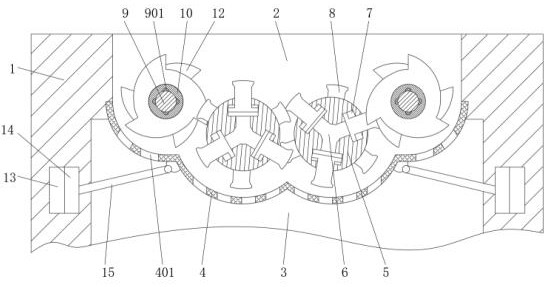
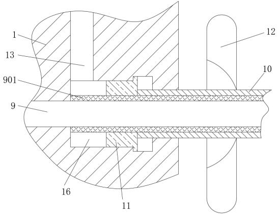
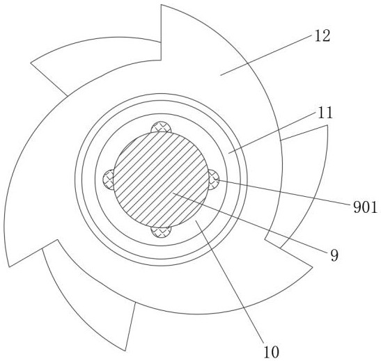
[0022] Reference Figure 1-Figure 2 As well as Figure 4There are four two -symmetrical passage channel 13 and stairway cavity 16 at both ends of the rack 1, a saturated hydraulic oil filled with the pressure channel 13 and the staircase 16Connect, there is a Pistons 14 on the other end of the event. The piston 14 is a fixed connection rod 15 at the end of the sub -ingredient 3, and the top of the connection rod 15 is hinged at the bottom of the sieve plate 4 to make the positive sieve board 4 4Torn blade 8 is close to 4 when the hydraulic oil is squeezed by the squeezing of the sieve. The tear blade here drives the scrap steel on the sieve 4 to the direction of the blade wheel II 12. At this time, Make Sieva 4 for irregular vibration, so that when the Sieve Board 4 is vibrated with rules, the piston 14 on both sides can drive the piston 14 to do irregular movement.The hydraulic oil within the side pressure channel 13 of the side enables the hydraulic oil to push the variable roller...


PUM


Abstract

The invention relates to the technical field of steel processing, and discloses a waste steel four-shaft shredding machine which comprises a rack, the middle of the rack is fixedly sleeved with a sieve plate, leaking holes are evenly formed in the sieve plate, and two symmetrical motors I are fixedly connected to the middle of one end of the rack; a motor I is fixedly connected to the base, blade wheels I which are evenly distributed are fixedly connected to an output shaft of the motor I, a hydraulic cavity is formed in the center of each blade wheel I, three movable cavities which are evenly distributed are formed in each blade wheel I, and shredding blades are movably connected into the movable cavities in a sleeved mode. Through the designed blade wheels I, blade wheels II and a sieve plate, after the two blade wheels I conduct preliminary crushing on the waste steel, the crushed waste steel can enter the meshed crushing part of the blade wheels I and the blade wheels II again under the limitation of the sieve plate and the driving of the blade wheels I and the blade wheels II, so that the waste steel is shredded multiple times, and the crushing efficiency is improved. And the shredded waste steel is discharged after reaching the qualified volume.

Description

Technical field [0001] The invention involves the field of steel processing technology, which is specifically a four -axis tear machine for waste steel. Background technique [0002] After the steel is used, it becomes a scrap steel, which needs to be crushed and recycled to smell into new qualified steel.Scrap steel to achieve the purpose of facilitating transportation and easy processing. [0003] The existing fragments are divided into single -axis, double -axis, three -axis, and four -axis tear machines. The working principle of the four -axis tear machine is the preliminary crushing of waste steel in the middle of the central part.Falling on the sieve plate below, the waste steel on the sieve plate is thrown by the blade, so that the waste steel will fall again on the blade part of each other, so that the scrap steel is crushed multiple times until the volume of the waste steel is up to the standard standard.Until the hole on the sieve board falls. [0004] There are still s...

Claims


Application Information

Patent Timeline
Patent Type & Authority Applications(China)
IPC IPC(8): B02C18/14B02C18/18B02C23/16
CPCB02C18/142B02C18/184B02C23/16B02C18/0084B02C2023/165B02C2201/06
Inventor 王卫兵
Owner 唐山谷润科技有限公司
Learn More