

Machining tool and machining process for thin-wall plate parts
A thin-walled plate and tooling technology, applied in metal processing equipment, metal processing machinery parts, manufacturing tools, etc., to improve processing efficiency, improve clamping efficiency, and reduce errors
Active Publication Date: 2022-06-10
HANGZHOU DAHE THERMO MAGNETICS CO LTD
View PDF7 Cites 0 Cited by
- Summary
- Abstract
- Description
- Claims
- Application Information
AI Technical Summary
Problems solved by technology
[0006]
In view of the cumbersome positioning steps of the thin-walled workpiece tooling in the prior art, it is difficult to ensure efficient processing of each surface of the workpiece after the thin-walled workpiece is clamped
Method used
View moreImage
Smart ImageViewing Examples

Examples
Embodiment 1
[0037] Except for the above-mentioned embodiments, within the scope disclosed in the claims and description of the present invention, the technical features of the present invention can be re-selected and combined to form new embodiments, which are all without the need for creative work by those skilled in the art. Therefore, these embodiments that are not described in detail in the present invention should also be regarded as specific embodiments of the present invention and fall within the protection scope of the present invention.
Embodiment 2
Login to View More PUM
 Abstract
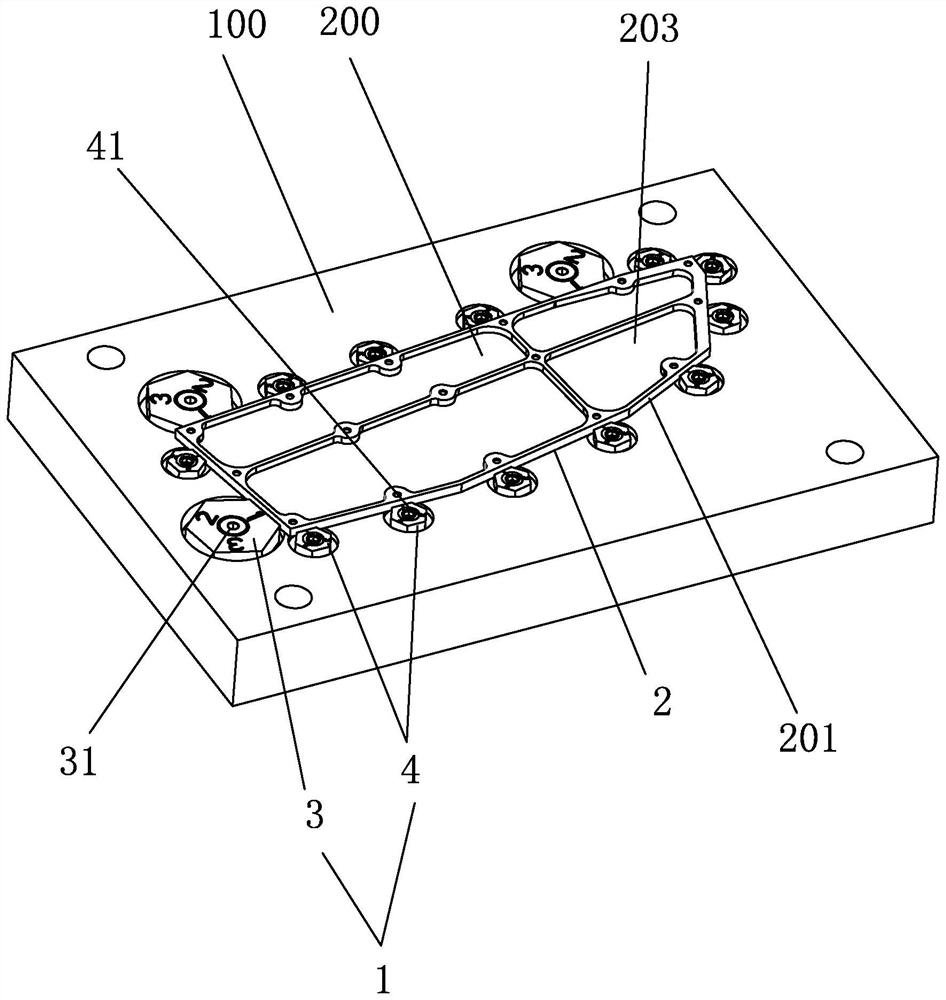
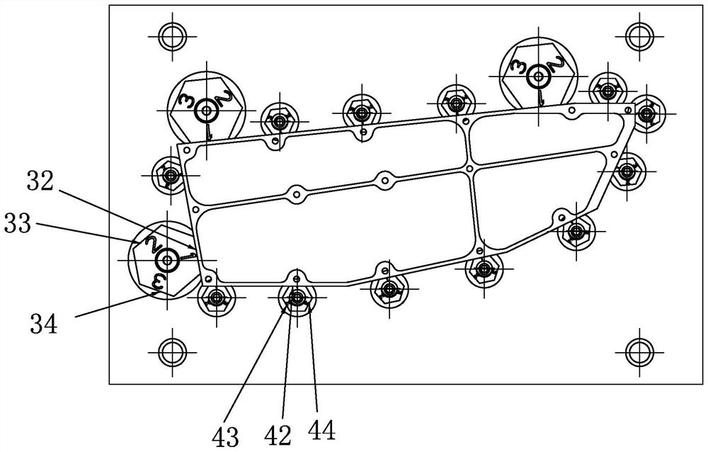
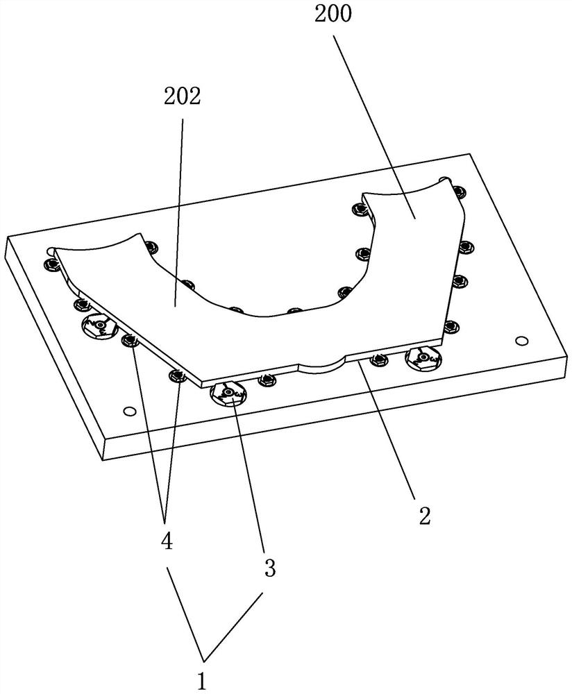
The invention discloses a machining tool for thin-wall plate parts, which comprises a tool base plate and a multi-precision mode positioning mechanism arranged on the tool base plate, a discharging cavity is arranged in the middle of the multi-precision mode positioning mechanism, and the multi-precision mode positioning mechanism can adjust the outer contour surface of the discharging cavity according to the machining precision requirement. The invention further discloses a machining process of the thin-wall plate type part, the multi-precision mode positioning mechanism arranged on the tool base plate is used for locking the part of the same specification, and the characteristic that the multi-precision mode positioning mechanism can adjust the outer contour face of the discharging cavity is utilized; in different machining procedures such as rough machining, semi-finish machining and finish machining, the workpiece can be accurately positioned, the clamping precision does not need to be frequently adjusted, the tool positioning workload is optimized, and the clamping and machining efficiency is remarkably improved.
Description
technical field [0001] The invention relates to the technical field of tooling fixtures, in particular to a processing tooling and processing technology for thin-walled plate parts. Background technique [0002] Thin-walled plate parts are widely used in semiconductor equipment, manipulators, vacuum and other fields because of their light weight, high strength, heat resistance and corrosion resistance. Such parts are large in size and thin in wall, and are prone to deformation during processing, and it is not easy to guarantee the size and shape tolerance of the parts. [0003] The traditional processing plan of thin-walled plate parts is: blanking-rough milling shape and sinking groove on the upper and lower surfaces (by back and forth pressing the plate)-stress relief heat treatment-fix the workpiece by sticking silica gel around it, semi-finish milling the upper and lower planes-finish milling Bottom sinker (through the inverted plate) - fix the workpiece by sticking sil...
Claims
Login to View More Application Information
Patent Timeline
 Patent Type & AuthorityApplications(China)
IPC IPC(8): B23Q3/06B23C3/00
CPCB23Q3/065B23C3/00
Inventor雷林光洪婧
OwnerHANGZHOU DAHE THERMO MAGNETICS CO LTD