A center frame device for machining aircraft landing gear and its clamping method

An aircraft landing gear and center frame technology, applied in metal processing equipment, metal processing mechanical parts, manufacturing tools, etc., can solve problems such as damage to the stability of the center frame structure, reduced workpiece machining accuracy, and surface cracks on the center frame. Improve work efficiency, ensure durability, and good plasticity

Active Publication Date: 2022-08-09
四川仨川航空科技股份有限公司
View PDF13 Cites 0 Cited by
  • Summary
  • Abstract
  • Description
  • Claims
  • Application Information

AI Technical Summary

Problems solved by technology

However, this traditional steady frame is generally made of cast iron, and its material is relatively hard. During the clamping process of the workpiece, it is often necessary to tap the steady frame to adjust its position. In the case of repeated knocking, it often causes surface cracks in the steady frame. , which damages the structural stability of the center frame
In addition, the traditional center frame often adopts an integral circular ring hinged structure, and the steps are more cumbersome when disassembling and unloading workpieces, thereby reducing work efficiency, and the ring joints are easy to wear after multiple disassembly and assembly of workpieces, reducing the clamping accuracy. Resulting in a reduction in the machining accuracy of the workpiece

Method used


Image

  • A center frame device for machining aircraft landing gear and its clamping method
  • A center frame device for machining aircraft landing gear and its clamping method

Examples


Embodiment Construction

[0028] The specific embodiments of the present invention are described below to facilitate those skilled in the art to understand the present invention, but it should be clear that the present invention is not limited to the scope of the specific embodiments. For those of ordinary skill in the art, as long as various changes Such changes are obvious within the spirit and scope of the present invention as defined and determined by the appended claims, and all inventions and creations utilizing the inventive concept are within the scope of protection.

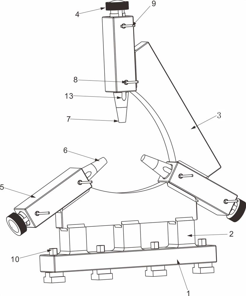
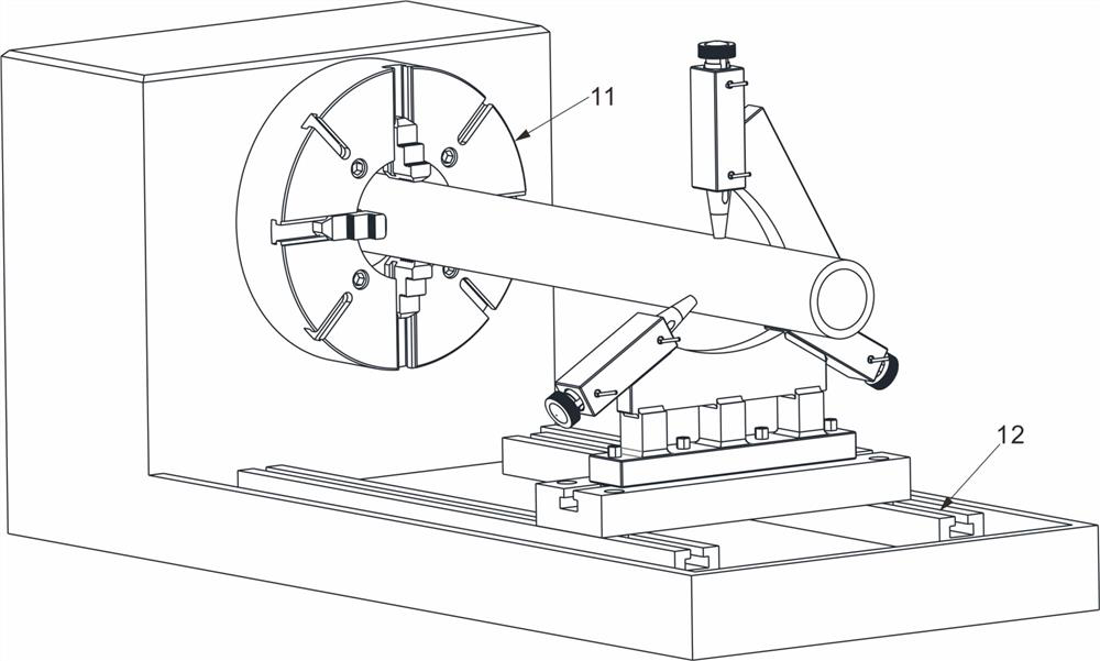
[0029] like figure 1 and figure 2 As shown, the center frame device for aircraft landing gear processing in this scheme includes a base 1, the upper end of the base 1 is provided with a center frame 3, the center frame 3 is an open ring structure, and both ends and the middle of the center frame 3 are provided with support arms 5. The three support arms 5 are evenly distributed at an angle of 120° on the annular structure, and ...


PUM


Abstract

The present invention disclosed a central frame device and its fixture method for aircraft landing rack processing. The central frame includes the base. The upper end of the base is set with a central frame.Set up the center of the support arm, and the three supporting arm points to the center of the ring structure, one of which is set up vertically; the three supporting arm is opened along the axis of the axis.Put the pores in the rod; the base is installed on the guide rail of the lathe. The center of the center of the center is parallel to the cable of the lathe.The processing method includes: step s1 :s8.The design structure of the present invention is simple, easy to load and unload and use, and is overall formed, one processing, and the overall structure is strong and accurate.The invention is accurately located during the part of the parts clip, and the offset error of the parts appears in real time during the processing process.

Description

technical field [0001] The invention relates to the technical field of numerical control machining, in particular to a center frame device for machining an aircraft landing gear and a clamping method thereof. Background technique [0002] For the clamping of the rotating parts of the aircraft landing gear, the lathe chuck is generally used to cooperate with the rear center of the tailstock. Sometimes, in order to ensure the accurate processing of the rotary body and the thin-walled outer cylinder, the purchased traditional center frame is generally used to clamp and fix the position of the workpiece. However, this kind of traditional center frame is generally made of cast iron, and its material is relatively hard. During the workpiece clamping process, it is often necessary to tap the center frame to adjust the position. In the case of repeated knocks, surface cracks often appear on the center frame. , so that the structural stability of the center frame is damaged. In add...

Claims


Application Information

Patent Timeline
Patent Type & Authority Patents(China)
IPC IPC(8): B23Q1/76
CPCB23Q1/763Y02T50/40
Inventor 姬广靖郭仕华赵志敏何博涛周松
Owner 四川仨川航空科技股份有限公司
Why Eureka
Try Eureka