Enhanced antenna structure of handheld communication equipment based on 5G technology application

A technology of communication equipment and antenna structure, which is applied to antennas, antenna parts, antenna supports/installation devices, etc., can solve the problems of poor antenna signal quality, poor use effect, low economic benefits, etc., to improve the signal enhancement effect , Improve the effect of signal transmission and reception, and improve the effect of structural stability

Inactive Publication Date: 2022-06-17
深圳市恒祥通天线技术有限公司
View PDF0 Cites 0 Cited by
  • Summary
  • Abstract
  • Description
  • Claims
  • Application Information

AI Technical Summary

Problems solved by technology

[0003] The existing antenna structure of handheld communication equipment based on 5G technology applications usually puts the communication chip inside the antenna during use, and places the antenna outside for effective signal transmission and reception. However, considering the protection chip, the communication chip It is sealed inside the antenna. Under the sealing condition, the effect of sending and receiving signals by the chip is actually reduced. At present, the operation of reducing the thickness of the antenna shell is used. However, in the case of thinning the antenna shell, the antenna loses its structural stability. The actual antenna The signal quality is poor, and the enhancement operation cannot be performed according to the actual situation, and the use effect is not good
[0004] In addition, the antenna structure of the existing handheld communication equipment based on 5G technology applications cannot be conveniently repaired after a period of use because the communication chip is placed inside the wire during use. The communication chip is sealed inside the antenna housing, which cannot be disassembled and replaced. Usually, it is replaced directly or the housing is cut and removed. While the operation is troublesome, it cannot be recycled. The economic benefit is low and the use effect is not good.

Method used


Image

  • Enhanced antenna structure of handheld communication equipment based on 5G technology application
  • Enhanced antenna structure of handheld communication equipment based on 5G technology application
  • Enhanced antenna structure of handheld communication equipment based on 5G technology application

Examples


no. 1 example

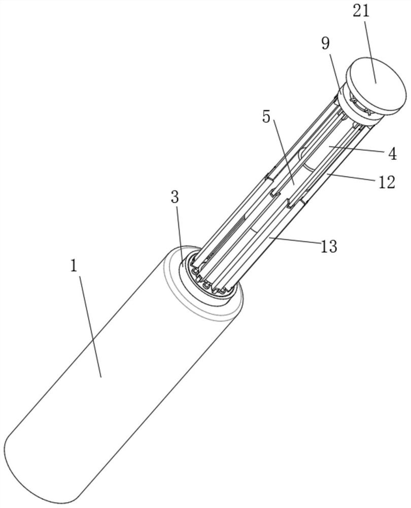
[0035] The first embodiment: as figure 1 , figure 2 , image 3 , Figure 4 and Figure 5 As shown in the figure, the cover plate 21 is rotated upward, so that the cover plate 21 drives the fixed rod 4, the mounting seat 3 and the limit seat 2 to rotate, thereby making the limit seat 2 rotate upward, and the positioning rod 19 is removed from the thread at the bottom of the limit seat 2. Move out of the slot 20, with the rise of the fixed rod 4, the first plate 12 and the second plate 13 move out of the housing 1 and move to the top, and make the top surface of the mounting seat 3 and the magnetic plate 17 adsorb, rotate the curved rod 26, The curved rod 26 drives the threaded ring 25 to move downward, so that the adjustment seat 9 pushes the first plate 12 to rotate, so that the connection between the first plate 12 and the second plate 13 moves outward, and the chip plate 5 is exposed on the outer surface of the fixing rod 4 out for enhanced signal reception.

[0036] F...

no. 2 example

[0039] Second embodiment: as figure 1 , figure 2 , image 3 , Figure 4 , Figure 5 and Figure 8 As shown in the figure, after the end signal is strengthened, the upper curved rod 26 is turned on, so that the first plate 12 and the second plate 13 are restored to the vertical state, and the cover plate 21 is screwed down, so that the fixed rod 4 drives the limit seat 2 to move downward , the threaded groove 20 on the bottom surface of the newspaper limit seat 2 is threadedly sleeved with the positioning rod 19, and before the positioning rod is completely selected into the threaded groove 20, gently rotate the curved rod 26 to make the adjustment seat 9 move downward slightly, and then Oh, the No. 1 plate 12 that is movably socketed at the bottom of the adjusting seat 9 swings outward. With the downward movement and swinging of the No. 1 plate 12, the No. 2 plate 13 is driven to follow the swing, and the No. 1 plate 12 and the No. 2 plate 13 are located in the position. ...

no. 3 example

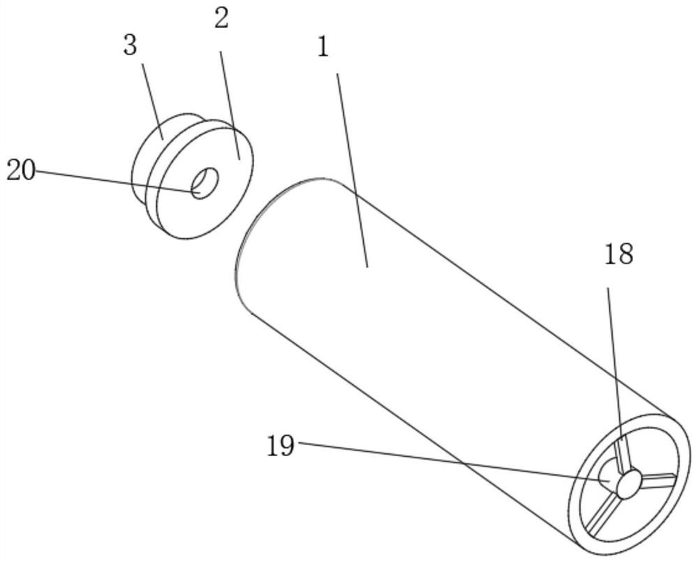
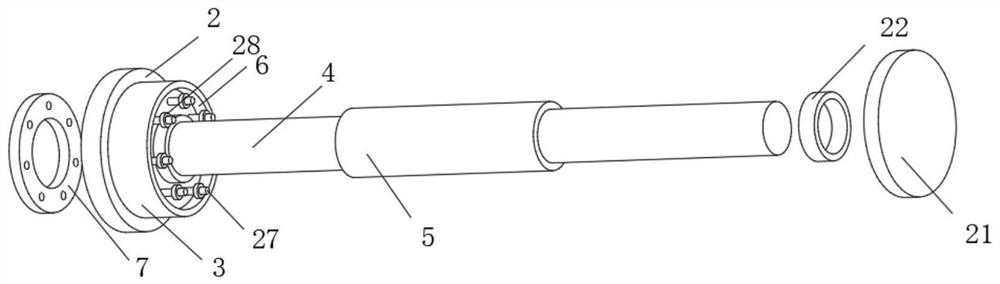
[0046] The third embodiment: as figure 1 , image 3 and Figure 4 As shown, when the chip board 5 needs to be repaired or replaced, after the cover plate 21 is rotated outward, and the fixing rod 4 is connected to the chip board 5 and moved to the outside of the housing 1, the locking cap 28 is loosened, and the fixing rod is kept 4. Without moving, rotate the cover plate 21, so that the sleeve 22 at the bottom of the cover plate 21 is unscrewed from the top of the fixing rod 4, and the threaded ring 25 is rotated outward, so that the threaded ring 25 is unscrewed from the upper end of the fixing rod 4, and at the same time drives the The movable seat 7 slides out of the fixed rod 4, and the chip board 5 is removed from the fixed rod 4 for inspection and replacement.

[0047] First, by using the top hole on the top surface of the housing 1 to be threadedly connected to the fixing rod 4, the fixing rod 4 can be unscrewed from the housing 1, and the movable seat 7 can be remov...


PUM


Abstract

The invention belongs to the technical field of antenna structures, and discloses a handheld communication equipment enhanced antenna structure based on 5G technology application, which comprises a shell, the inner surface of the shell is movably sleeved with a limiting seat, the top surface of the limiting seat is fixedly connected with a mounting seat, and the top surface of the mounting seat is fixedly connected with a fixed rod. A movable seat is additionally arranged on the top surface of a mounting seat, the outer surface of a fixed rod is in threaded sleeve connection with a threaded ring, and an adjusting seat sleeving the threaded ring is connected with a first plate and is matched with a second plate movably sleeving the first plate, so that both the first plate and the second plate can rotate; the connecting positions of the first plates and the second plates are made to move towards the outer side by screwing down the threaded rings, opening of the multiple sets of the first plates and the second plates is achieved, and therefore the chip plates fixedly connected to the outer surfaces of the fixing rods in a sleeving mode are leaked out, blocking of the thick shell is avoided, the actual signal receiving and transmitting effect is improved, the signal enhancing effect is improved, and the use effect is good.

Description

technical field [0001] The invention belongs to the technical field of antenna structures, in particular to an enhanced antenna structure of a handheld communication device based on 5G technology application. Background technique [0002] The fifth generation mobile communication technology is a new generation of broadband mobile communication technology with high speed, low delay and large connection. It is used to improve the actual communication quality and expand the communication effect. [0003] In the existing antenna structure of handheld communication equipment based on 5G technology application, during use, the communication chip is usually built into the antenna, and the antenna is placed outside for effective signal transmission and reception. However, considering the protection of the chip, the communication chip It is sealed inside the antenna. Under the sealing condition, the effect of the chip sending and receiving signals is actually reduced. At present, th...

Claims


Application Information

Patent Timeline
Patent Type & Authority Applications(China)
IPC IPC(8): H01Q1/22H01Q1/12H01Q1/24H01Q1/42
CPCH01Q1/2283H01Q1/42H01Q1/1235H01Q1/243
Inventor 陆海兰孔祥铭
Owner 深圳市恒祥通天线技术有限公司
Why Eureka
Try Eureka