Retaining ring adjusting device of vertical roller mill

A technology of adjusting device and retaining ring, applied in the direction of grain processing, etc., can solve the problems of destroying the stability of the material layer, reducing the current of the mill, and reducing the grinding efficiency of the mill.

Pending Publication Date: 2022-06-21
TIANJIN CEMENT IND DESIGN & RES INST
View PDF0 Cites 0 Cited by
  • Summary
  • Abstract
  • Description
  • Claims
  • Application Information

AI Technical Summary

Problems solved by technology

A large amount of fine powder remains at the bottom of the grinding disc, which increases the fluidity of the material layer, thus destroying the stability of the material layer. On the one hand, it causes the vibration of the mill, and on the other hand, it reduces the grinding efficiency and the current of the mill, which leads to the decrease of the mill table time and the electric current. At the same time, due to the increase in the internal circulation load of the mill, the particle gradation of the finished product is narrowed, which affects the quality and performance of the finished product
[0006] In the prior art, the height of the retaining ring can be adjusted up and down. However, although the height of the retaining ring can be reduced to more than 50% at most, there are still some retaining rings.
In fact, the content of fine powder in the lower layer of the retaining ring is the most in the material after grinding by the grinding roller. Reducing the height of the retaining ring can only alleviate the destructive effect of the fine powder at the bottom of the material layer on the stability of the material layer to a certain extent. Until it is completely solved, the root of the problem lies in the physical conflict between the height of the retaining ring and the two variables of mill stability and grinding efficiency, that is, to improve the stability of the mill and the output of the mill, the height of the retaining ring needs to be increased. However, the grinding efficiency of the mill is reduced; if the grinding efficiency of the mill is improved, the height of the retaining ring must be reduced, but the output and stability of the mill are affected

Method used


Image

  • Retaining ring adjusting device of vertical roller mill
  • Retaining ring adjusting device of vertical roller mill
  • Retaining ring adjusting device of vertical roller mill

Examples


Embodiment 1

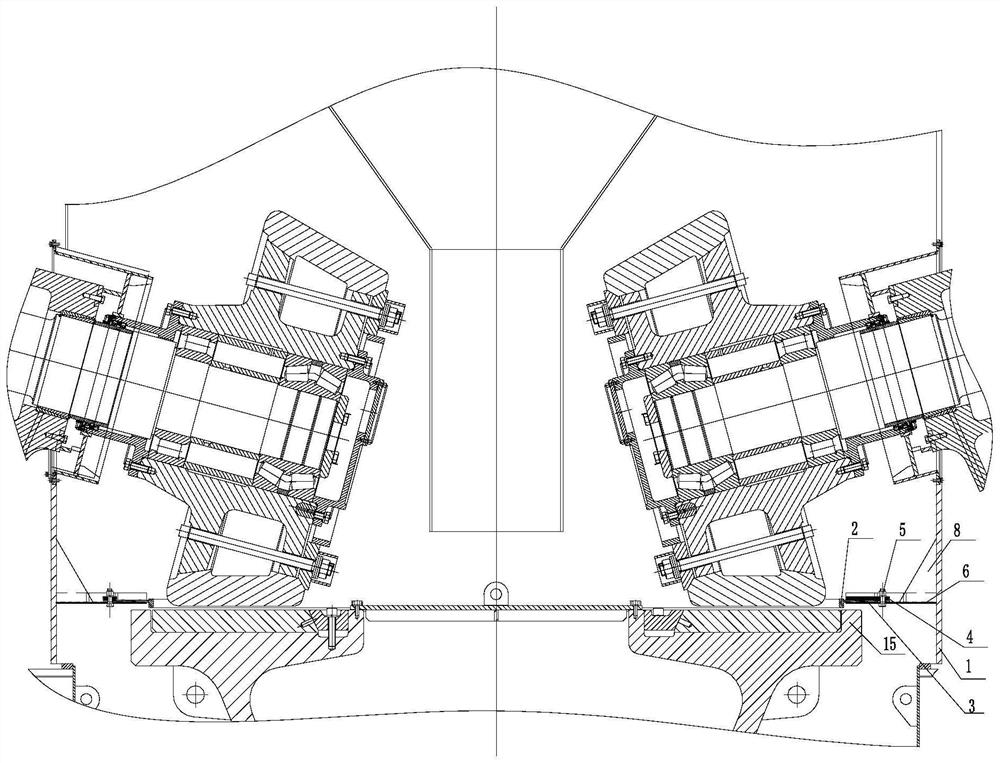
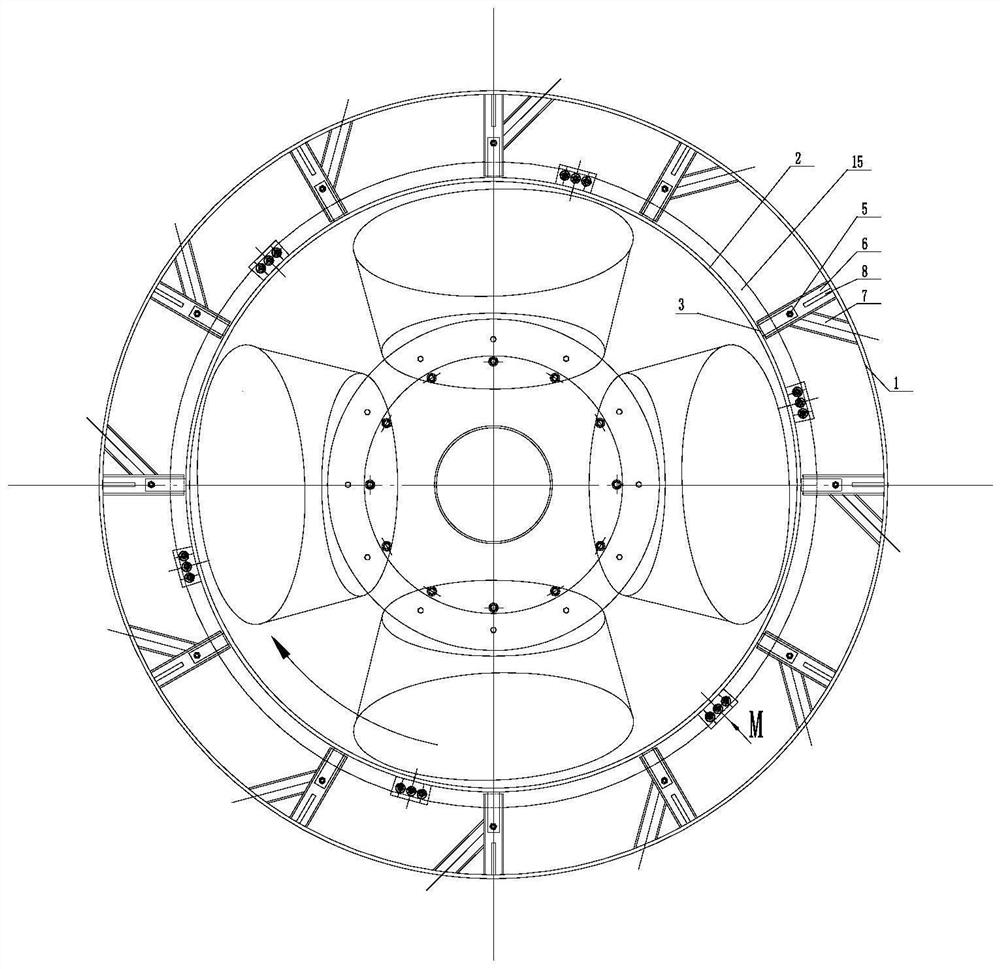
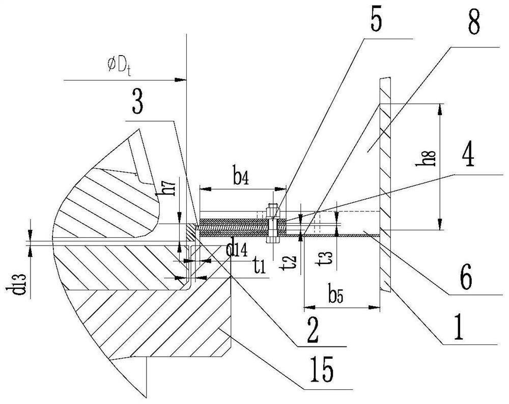
[0034] Example 1, see Figure 1 to Figure 6 , a vertical roller mill retaining ring adjustment device, including a mill shell, a grinding disc 15, several grinding rollers, a blanking cone and a retaining ring 2; the outer side of the retaining ring is installed with the retaining ring and the A retaining ring adjustment mechanism is formed between the grinding discs to form a fine powder discharge gap. In this embodiment, the baffle ring adjustment mechanism adopts a built-in baffle ring adjustment mechanism, and the built-in baffle ring adjustment mechanism is installed in the shell 1 of the mill; The retaining ring support 3, the above retaining ring support can be installed on the upper or lower part of the radial support according to the needs of the gap between the retaining ring and the grinding disc; several height adjustment pads are arranged above the retaining ring support 4. The number and vertical position of the above-mentioned height adjustment plates can be ad...

Embodiment 2

[0039] Example 2, see Figure 7 to Figure 9 , a vertical roller mill retaining ring adjustment device, including a mill shell, a grinding disc, several grinding rollers, a blanking cone and a retaining ring 2; A retaining ring adjustment mechanism forming a fine powder discharge gap between them. In this embodiment, the baffle ring adjustment mechanism adopts an external baffle ring adjustment mechanism; the external adjustment device is installed outside the shell 1 in the mill; it includes a baffle ring welded on the outer wall of the baffle ring in the radial direction The support 3, the retaining ring support is fixedly installed on the radial support 6 through the fastener 5, and the radial support upper rib 9 is welded on the upper surface of the radial support near the shell side of the mill. There is a chute 1-1 on the shell of the mill at the position corresponding to the upper rib of the radial support; the upper rib of the radial support is an L-shaped structure; ...


PUM


Abstract

The invention discloses an adjusting device for a retainer ring of a vertical roller mill. A built-in adjusting mechanism is arranged in a shell in the mill; the device is characterized by comprising a retaining ring and a retaining ring support, the retaining ring support is welded on the outer wall of the retaining ring along the radial direction, a plurality of height adjusting base plates are arranged above the retaining ring support, the height adjusting base plates and the retaining ring support are fixedly mounted on a radial support through fasteners, and the outer end of the radial support is welded on the inner wall of a shell in the mill. According to the invention, the material retaining ring and the millstone can be separated in space, the material retaining ring originally rotating along with the millstone is suspended above the millstone and is statically supported by the bracket welded in the shell in the mill, and a fine powder discharging gap is formed between the material retaining ring and the millstone, so that fine powder can be discharged.

Description

technical field [0001] The invention belongs to the technical field of vertical roller mill design, and in particular relates to a vertical roller mill stopper ring adjusting device. Background technique [0002] Vertical roller mill is referred to as vertical mill. [0003] The working principle of the existing structure is as follows: under the action of gravity, the new feeding material and the returning material of the powder separator are fed into the middle of the grinding table from the silo, the grinding table rotates to drive the material to rotate, and the material moves from the middle of the grinding table to the edge of the grinding table under the action of centrifugal force. When moving to the bottom of the grinding roller, the grinding roller squeezes the material (material layer) under the combined action of the force F and the retaining ring, the material is ground, and the ground material passes over the retaining ring under the action of centrifugal force...

Claims


Application Information

Patent Timeline
Patent Type & Authority Applications(China)
IPC IPC(8): B02C15/00
CPCB02C15/003B02C2015/002
Inventor 豆海建孙建宋留庆秦中华李铭哲
Owner TIANJIN CEMENT IND DESIGN & RES INST
Why Eureka
Try Eureka