Method for mounting shaft, in particular camshaft, in bearing guide rail of internal combustion engine

A technology for bearing guide rails and internal combustion engines, which is applied in the directions of engine seals, valve devices, mechanical equipment, etc., can solve the problems of inability to install space in the engine compartment and other problems.

Pending Publication Date: 2022-06-21
MAHLE INT GMBH
View PDF1 Cites 0 Cited by
  • Summary
  • Abstract
  • Description
  • Claims
  • Application Information

AI Technical Summary

Problems solved by technology

[0003] However, the method known from the prior art has the disadvantage that pressing the seal ring into the associated groove on the camshaft using the calibration tool described therein requires a specific axial path of travel, which is generally not possible in modern Implementation in the engine compartment and therefore often not possible in tight installation spaces

Method used


Image

  • Method for mounting shaft, in particular camshaft, in bearing guide rail of internal combustion engine
  • Method for mounting shaft, in particular camshaft, in bearing guide rail of internal combustion engine
  • Method for mounting shaft, in particular camshaft, in bearing guide rail of internal combustion engine

Examples


Embodiment Construction

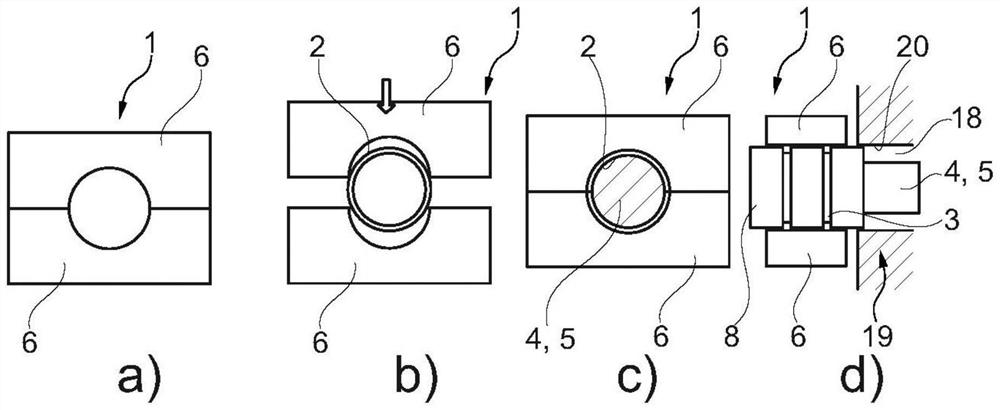
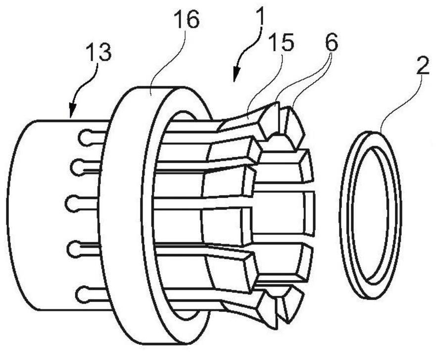
[0037] according to Figure 1 to Figure 7 , shows a calibration tool 1 according to the invention, by means of which the sealing ring 2 can be calibrated or compressed so as to be pressed into the groove 3 of the shaft 4 (eg camshaft 5 ) (see figure 1 b to figure 1 d. figure 2 b and figure 2 c and Figure 4 ). The calibration tool 1 here has at least two radially displaceable, partially circular clamping jaws 6 (according to the figure 1 a to figure 1 d is the two jaws 6, according to figure 2 a to figure 2 c is the three jaws 6, according to image 3 A total of eleven jaws 6). on the basis of Figure 5 to Figure 7 In the case of the calibration tool 1 , the calibration tool has a displaceable belt clip 7 , with which a reduction in the diameter D of the sealing ring 2 can be achieved by shrinking.

[0038] The method according to the invention for mounting the shaft 4 in the bearing guide 18 of the internal combustion engine 19 is constructed as follows: First,...


PUM


Abstract

The invention relates to a method for mounting a shaft (4), in which at least one sealing ring (2) is mounted on the shaft (4) such that the at least one sealing ring engages in a circumferential groove (3). The invention is characterized in that a calibration tool (1) having at least two radially displaceable partially circular clamping jaws (6) or a belt clamp (7) is used in order to press the sealing ring (2) into the corresponding groove (3) and to hold it in a force-fit and form-fit manner.

Description

technical field [0001] The invention relates to a method for mounting a shaft in a bearing guide of an internal combustion engine according to the preamble of claim 1, wherein at least one sealing ring is mounted on the shaft such that the at least one sealing ring is expanded and pushed onto the region of the shaft . The invention also relates to an expansion tool for expanding a sealing ring for such a method and a calibration tool for use in such a method. Background technique [0002] A general method for mounting a camshaft in a bearing guide of a cylinder head cover of an internal combustion engine is known from DE 10 2016 224 040 A1, wherein the following steps are performed: at least one sealing ring is mounted on the camshaft such that at least one sealing ring The ring is pushed onto the area of ​​the cam in which at least one radial circumferential groove is formed on the outer diameter of the camshaft, so that the sealing ring is arranged in the groove. The sea...

Claims


Application Information

Patent Timeline
IPC IPC(8): B25B27/00B25B27/02
CPCB25B27/0092B25B27/02F16J15/3268B25B27/0028F01L1/047F01L2001/0476F16J15/32F01L2303/02F01L2303/01
Inventor 斯蒂芬·克莱默弗兰克·多泰尔贾斯特斯·希姆施泰特
Owner MAHLE INT GMBH
Why Eureka
Try Eureka