Light path calibration module

A technology for calibrating optical paths and calibrating light beams, which is applied in the field of optical sensing, can solve problems such as distortion, photoelectric sensor failure, and accuracy degradation, and achieve the effects of facilitating production assembly or production line application testing, improving production efficiency, and ensuring output power

Pending Publication Date: 2022-06-21
广州德擎光学科技有限公司
View PDF0 Cites 0 Cited by
  • Summary
  • Abstract
  • Description
  • Claims
  • Application Information

AI Technical Summary

Problems solved by technology

A photoelectric sensor that detects the quality of laser processing generally includes a housing, a spectroscopic element, and a photosensitive element. Photoelectric induction signal; but in the actual use process, when the photoelectric sensor is used for a long time, the accuracy of optical detection will decrease. For example, some photodiodes and other devices in the multi-channel spectrum may cause the detection signal " Attenuation" or "Distortion"
[0003] The detection signal of the photoelectric sensor of the original equipment is "attenuated" or "distorted". ", it belongs to normal attenuation, and the equipment is not faulty; 2. The photoelectric sensor fails, which belongs to abnormal attenuation; 3. The equipment vibrates, or after disassembly and assembly, the laser processing signal has a certain deviation

Method used


Image

  • Light path calibration module
  • Light path calibration module
  • Light path calibration module

Examples


Embodiment 2

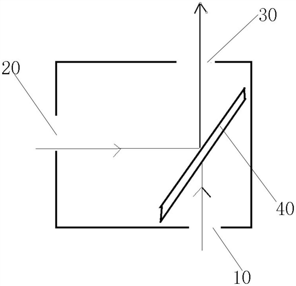
[0048] Example 2: as figure 1 , Figure 3-10 As shown, an optical path calibration module 1 is provided with a first light entrance port 10, a second light entrance port 20 and a first light exit port 30, and a first light splitting device 40 is provided inside it.

[0049] The first light entrance 10 first receives the calibration beam of the calibration light source, when the calibration is completed, the calibration light source is removed, and the first light entrance 10 is closed to prevent external stray light from entering the photoelectric sensor through the calibration module 1;

[0050] The second light entrance 20 receives the light beam of the target light source;

[0051] The first light outlet 30 emits a detection beam to the photoelectric sensor;

[0052] The first light splitting device 40 forms an included angle of 45° with both the first light entrance port 10 and the second light entrance port 20 .

[0053] In this embodiment, the first beam splitting dev...

Embodiment 3

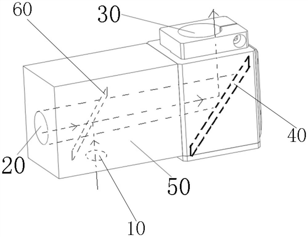
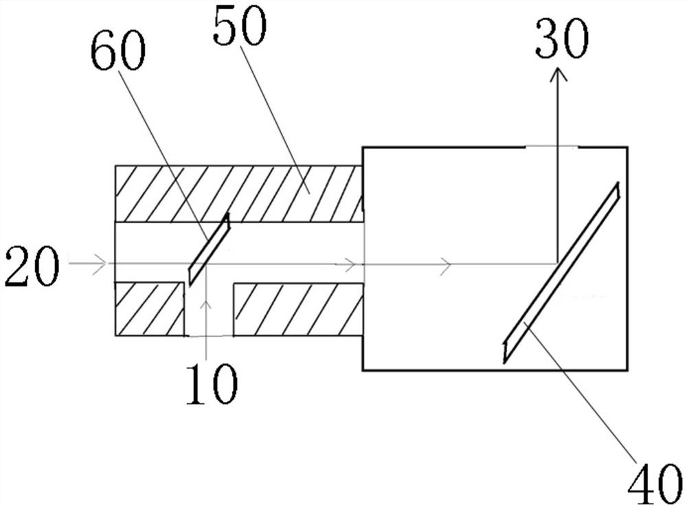
[0058] Example 3: as Figure 2-10 As shown, an optical path calibration module 1 is provided with a first light entrance port 10, a second light entrance port 20, a first light exit port 30, a T-shaped cavity structure 50, and a first light splitting device 40 is arranged inside it, and The second light splitting device 60, in this case, the T-shaped cavity structure 50 is installed on the left side of the calibration module described in Embodiment 1, and the cavity on the right side of the T-shaped cavity structure 50 passes through the second light entrance port of Embodiment 1 20 is connected to the first light splitting device 40 , the left cavity of the T-shaped cavity structure 50 is the second light entrance 20 , the lower cavity is the first light entrance 10 , and the right cavity is connected to the first light splitting device 40 , so that the light beam of the cavity on the right side is reflected to the first light outlet 30 after passing through the first beam sp...

Embodiment 4

[0066] Embodiment 4: In this embodiment, the difference from Embodiment 3 is that the second spectroscopic device is replaced with a total reflection mirror 60, and the total reflection mirror 60 is inserted and installed in the T-shaped cavity structure 50 through the first light entrance 10. At the inner corner, an included angle of 45° is formed with the first light entrance port 50 and the second light entrance port 20 . On the one hand, the calibration beam from the first light entrance 10 is completely reflected, and is reflected by the first beam splitting device 40. The reflected calibration beam is emitted from the first light outlet 30 and received by the photoelectric sensor, which maximizes the calibration beam On the other hand, when the target light source beam enters the T-shaped cavity structure 50 from the second light entrance 20, the all-reflection mirror 60 reflects all the target light source beam upward, eliminating the interference of the target light sou...


PUM


Abstract

The invention discloses a light path calibration module which is provided with a first light inlet, a second light inlet and a first light outlet, a first light splitting device is arranged in the light path calibration module, and the first light inlet is used for receiving a calibration light beam of a calibration light source or is closed; the second light inlet is used for receiving a light beam of the target light source or receiving a calibration light beam of the calibration light source; the first light outlet is used for emitting a detection light beam to the photoelectric sensor; the first light splitting device forms an included angle of 45 degrees with the first light inlet and the second light inlet, and the light path calibration module can judge whether a detection signal of a photoelectric sensor of original equipment is attenuated or distorted due to the damage of the photoelectric sensor, and can adjust a light path at the same time. The light path calibration module can be externally connected with a detachable T-shaped cavity structure according to different production line environments, so that the installation position of the calibration light source is changed, production assembly or production line application testing is facilitated, and the production efficiency is effectively improved.

Description

technical field [0001] The invention relates to the field of optical sensing, and more particularly to an optical path calibration module. Background technique [0002] A photoelectric sensor generally includes three parts: a photoelectric sensor, an optical path calibration module, and a light source module. The photoelectric sensor for detecting the quality of laser processing generally includes a casing, a spectroscopic element, a photosensitive element, etc. Its working principle is to separate the incident light into at least two spectrums through the built-in multi-component optical element, and receive and output the corresponding photodiode through the beam splitting optical path. Photoelectric induction signal; but in the actual use process, when the photoelectric sensor is used for a long time, the accuracy of optical detection will decrease. For example, some devices such as photodiodes in the multi-channel spectrum may be aging due to long-term use and other prob...

Claims


Application Information

Patent Timeline
Patent Type & Authority Applications(China)
IPC IPC(8): G01J1/42G01J1/02G01J1/04
CPCG01J1/4257G01J1/0295G01J1/0403G01J2001/444G01J2001/446G02B27/14G02B7/1825G01J1/0228G01J1/0414G01J1/08G01J1/0271G01J1/0411
Inventor 薛强周泉刘文杰
Owner 广州德擎光学科技有限公司
Why Eureka
Try Eureka