Electric traction device with positioning function

An electric traction and functional technology, applied in transportation and packaging, cable laying equipment, thin material handling, etc., can solve the problems of inconvenient fixing and center positioning, cumbersome operation process, right-angle bending of cables, etc., and achieve good cable traction effect , increase the contact area, reduce the effect of work intensity

Active Publication Date: 2022-06-21
山东五洲电力工程有限公司
View PDF9 Cites 2 Cited by
  • Summary
  • Abstract
  • Description
  • Claims
  • Application Information

AI Technical Summary

Problems solved by technology

[0005] In order to overcome the problem of cable traction for multiple protective tubes, the operator needs to install multiple guide wheels. The operation process is cumbersome. Placing the cable tractor under the cable well will cause the cable to bend at a right angle, which will easily cause damage to the cable. The disadvantage of the traction machine at the bottom of the cable well is that it is inconvenient to fix and centrally locate. An electric traction device with a positioning function that is convenient for fixing cables is provided.

Method used


Image

  • Electric traction device with positioning function
  • Electric traction device with positioning function
  • Electric traction device with positioning function

Examples


Embodiment 1

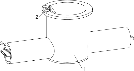
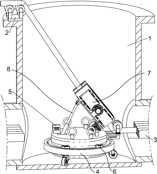
[0029] When this device needs to be used, one situation: when it is necessary to perform threading operation from the cable shaft 1 to the underground pipe on one side, the operator passes the right end of the cable through the traction mechanism 7, and then the operator starts the traction mechanism 7 to clamp the cable After the cable clamping is completed, the operator places the guide assembly 2 on the right side of the upper part of the cable well 1, and places the cable above the guide assembly 2, and then the operator uses one end of the rope to place the four ends on the directional locking mechanism 4. The operator puts the device into the cable well 1 through the rope, and at the same time the right part of the clamped cable is pulled into the cable well 1. When the device is placed in the cable well 1, the operator puts the rope in his hand Place it at the wellhead of the cable well 1, then the operator enters the cable well 1 and passes one end of the cable through ...

Embodiment 2

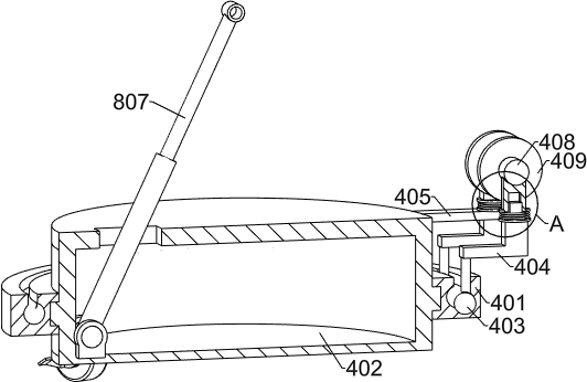
[0033] like Figure 7 As shown, the fixed assembly includes a sealing sleeve 612, and the sealing sleeve 612 is welded on the right part of the slide bar 611, and the right end of the slide bar 611 is fixedly connected with an air pressure sensor, and the air pressure sensor is electrically connected with the console 5, and the outer end of the slide bar 611 The air pressure sensor is located in the sealing sleeve 612, and the right part of the sealing sleeve 612 is slidably provided with a second limiting sleeve 613, and a first spring 614 is welded between the second limiting sleeve 613 and the sealing sleeve 612. The spring 614 is located in the sealing sleeve 612, and the right part of the second limiting sleeve 613 is fixedly connected with a clamping block 615. The clamping block 615 is set as a cavity, and the cavity of the clamping block 615 and the second limiting sleeve 613 Connected, the outer surfaces of the four clamping blocks 615 are all set to be arc-shaped, an...


PUM


Abstract

The invention relates to the technical field of cable installation, in particular to an electric traction device with a positioning function. The technical problems that when cable traction needs to be carried out on a plurality of protection pipes, an operator needs to install a plurality of guide wheels, the operation process is tedious, a cable is bent in a right-angle mode when a cable traction machine is placed under a cable well, so that the cable is prone to being damaged, and the traction machine placed at the bottom of the cable well is inconvenient to fix and carry out center positioning are solved. An electric traction device with a positioning function comprises a directional locking mechanism. A fixing mechanism is arranged on the directional locking mechanism, a traction mechanism is arranged on the upper portion of the fixing mechanism, and an angle adjusting mechanism is arranged on the traction mechanism. Through cooperation of the directional locking mechanism and the fixing mechanism, the directional locking mechanism is fixed and centered, cable angle adjustment is completed through the angle adjusting mechanism, the situation that the cable at the position of the positioning sleeve is extruded and deformed is avoided, installation of a guide wheel is reduced, and the working intensity of operators is relieved.

Description

technical field [0001] The invention relates to the technical field of cable installation, in particular to an electric traction device with a positioning function. Background technique [0002] In the process of electric power construction, it is necessary to pull the cable from the cable drum to facilitate the laying of the cable. Pulling the cable from the cable drum requires a large force, so the cable pulling machine is generally used to assist the pulling of the cable. , thereby reducing the labor force of workers. [0003] When laying wires for some circular cable wells, there are currently two ways to transport cables from the cable wells to the protective pipes of underground pipelines. The guide wheels are installed at one place to reduce the friction between the cable and the protective tube. The operator starts the cable pulling machine to pull the cable. When it is necessary to pull the cable on multiple protective tubes, the operator needs to install multiple ...

Claims


Application Information

Patent Timeline
IPC IPC(8): H02G1/06B65H51/14
CPCH02G1/06B65H51/14B65H2701/34
Inventor 纪建民刘道忠厉恩强井维波毕延亮孟繁昌
Owner 山东五洲电力工程有限公司
Why Eureka
Try Eureka