Receiving end power grid generator reactive standby optimization method and system

A receiving-end power grid and optimization method technology, applied in the direction of electrical components, circuit devices, AC network circuits, etc., can solve problems such as reducing system voltage stability, improve accuracy and convergence speed, improve voltage stability, and adjust efficiently Effect

Pending Publication Date: 2022-06-21
ELECTRIC POWER RESEARCH INSTITUTE OF STATE GRID SHANDONG ELECTRIC POWER COMPANY +1
View PDF0 Cites 0 Cited by
  • Summary
  • Abstract
  • Description
  • Claims
  • Application Information

AI Technical Summary

Problems solved by technology

The DC transmission not only has no voltage support capability, but needs to absorb a lar

Method used


Image

  • Receiving end power grid generator reactive standby optimization method and system
  • Receiving end power grid generator reactive standby optimization method and system
  • Receiving end power grid generator reactive standby optimization method and system

Examples


Example Embodiment

[0052] Example 1

[0053] The present embodiment discloses a method for optimizing the reactive power reserve of the generator at the receiving end, including:

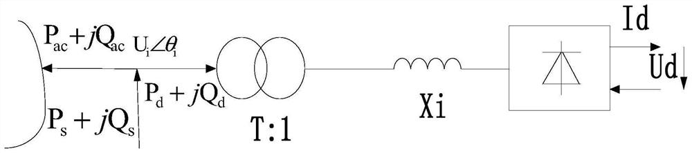
[0054] Step (1): analyze the fuzzy characteristics of the receiving-end power grid, use the trapezoidal membership function to characterize the uncertainty of the receiving-end new energy output and HVDC reactive power consumption, and calculate the fuzzy power flow of the receiving-end power grid;

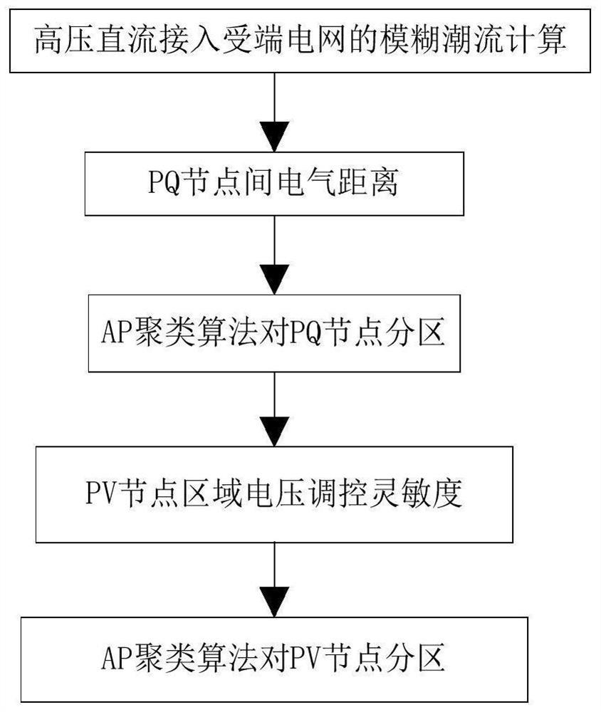
[0055] Step (2): Calculate the electrical distance between the PQ nodes of the power grid and the voltage regulation sensitivity of the PV node area, and use the AP clustering algorithm to partition the power grid to obtain an independent power grid area with electrical distance decoupling;

[0056] Step (3): based on the weight coefficient of the product of the node participation factor and the limit surface normal vector index, calculate the generator node reactive power reserve weight coefficient;

[0057] Step (4): in ...

Example Embodiment

[0156] Embodiment 2

[0157] The purpose of this embodiment is to provide a computing device, including a memory, a processor, and a computer program stored in the memory and running on the processor, and the processor implements the steps of the above method when the processor executes the program.

Example Embodiment

[0158] Embodiment 3

[0159] The purpose of this embodiment is to provide a computer-readable storage medium.

[0160] A computer-readable storage medium having a computer program stored thereon, the program executing the steps of the above method when executed by a processor.


PUM


Abstract

The invention provides a receiving-end power grid generator reactive standby optimization method and system, and the method comprises the steps: representing the uncertainty of extra-high voltage direct current consumed reactive power and new energy output through a trapezoidal membership function, and calculating the fuzzy power flow of a receiving-end power grid; partitioning the receiving-end power grid based on the fuzzy power flow of the receiving-end power grid; calculating a generator node reactive standby weight coefficient based on the receiving end power grid fuzzy power flow; in the subarea of the receiving end power grid, establishing a fuzzy motor reactive power reserve optimization model by using the generator node reactive power reserve weight coefficient; and solving the fuzzy motor reactive power reserve optimization model to obtain the optimal receiving end power grid generator reactive power reserve of the model. And the target optimization precision and the convergence speed are improved.

Description

technical field [0001] The invention belongs to the technical field of reactive power optimization of power systems, and in particular relates to a method for optimizing reactive power backup of generators in a receiving-end power grid considering the uncertainty of ultra-high voltage and new energy. Background technique [0002] The statements in this section merely provide background information related to the present invention and do not necessarily constitute prior art. [0003] Reactive power reserve refers to the maximum available reactive power that the system can issue when the grid is disturbed. Reactive power reserve is one of the important conditions to maintain voltage stability, power angle stability and power quality, and plays an important role in maintaining the safe and stable operation of the power grid and avoiding voltage collapse. According to the different action time scales, it can be divided into static reactive power reserve and transient reactive p...

Claims


Application Information

Patent Timeline
IPC IPC(8): H02J3/50H02J3/48H02J3/06
CPCH02J3/50H02J3/48H02J3/06H02J2203/10H02J2203/20H02J2300/28
Inventor 刘文学杨冬马欢张冰蒋哲梁正堂房俏李山周宁赵康张志轩田浩郝旭东程定一麻常辉汪挺
Owner ELECTRIC POWER RESEARCH INSTITUTE OF STATE GRID SHANDONG ELECTRIC POWER COMPANY
Why Eureka
Try Eureka