Nasal cavity irrigator
A technology for nasal irrigation and irrigation tubes, applied in bathing devices, physical therapy, etc., can solve the problems of no waste liquid, air pollution, etc., and achieve the effects of avoiding pollution, high safety, and reducing costs
- Summary
- Abstract
- Description
- Claims
- Application Information
AI Technical Summary
Problems solved by technology
Method used
Image
Examples
Embodiment 1
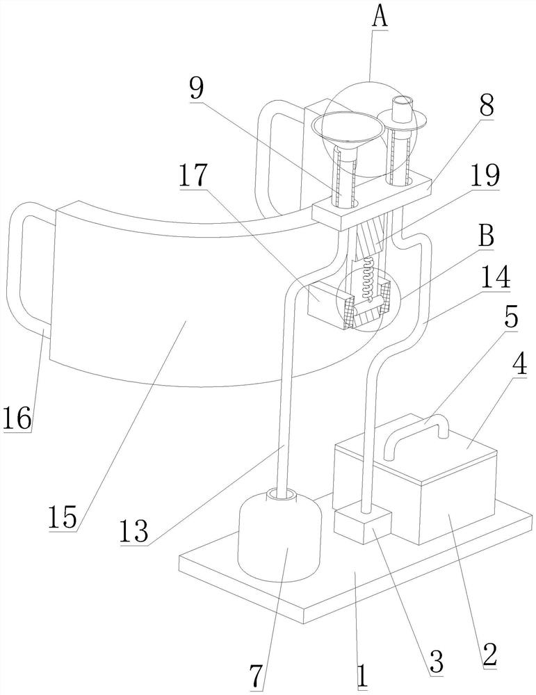
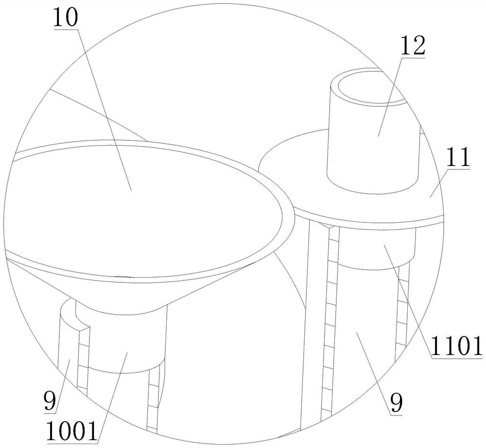
[0030] like figure 1 and Figure 4 As shown, a nasal irrigator proposed by the present invention includes a placing plate 1 , a box cover 4 , a handle 5 , a heating pipe 6 , a mounting plate 8 , a recovery tray 10 , a tray 11 , a waste liquid pipe 13 and a connecting pipe 14 . The placing plate 1 is provided with a liquid storage tank 2 , a micro pump 3 and a waste liquid bottle 7 , and the micro pump 3 communicates with the liquid storage tank 2 . The tank cover 4 is arranged on the liquid storage tank 2, and the tank cover 4 is detachably connected to the liquid storage tank 2. By setting the tank cover 4, the aqueous solution of the nasal wash can be protected to avoid being polluted by exposure to the air for a long time. The heating pipe 6 is arranged at the bottom of the box cover 4, and the heating pipe 6 is located in the liquid storage tank 2. By setting the heating pipe 6, the aqueous solution of the nasal wash can be heated, thereby avoiding the irritating nasal ca...
Embodiment 2
[0036] like figure 1 and Figure 4 As shown, a nasal irrigator proposed by the present invention includes a placing plate 1 , a box cover 4 , a handle 5 , a heating pipe 6 , a mounting plate 8 , a recovery tray 10 , a tray 11 , a waste liquid pipe 13 and a connecting pipe 14 . The placing plate 1 is provided with a liquid storage tank 2 , a micro pump 3 and a waste liquid bottle 7 , and the micro pump 3 communicates with the liquid storage tank 2 . The tank cover 4 is arranged on the liquid storage tank 2, and the tank cover 4 is detachably connected with the liquid storage tank 2. By setting the tank cover 4, the aqueous solution of the nasal wash can be protected to avoid being polluted by exposure to the air for a long time. The heating pipe 6 is arranged at the bottom of the box cover 4, and the heating pipe 6 is located in the liquid storage tank 2. By setting the heating pipe 6, the aqueous solution of the nasal wash can be heated, thereby avoiding the irritating nasal ...
Embodiment 3
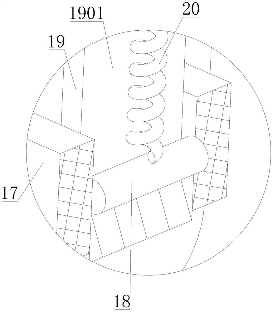
[0041] like figure 1 and Figure 4 As shown, a nasal irrigator proposed by the present invention includes a placing plate 1, a box cover 4, a handle 5, a heating pipe 6, a mounting plate 8, a recovery tray 10, a tray 11, a waste liquid pipe 13, a connecting pipe 14, a support Frame 15 , elastic band 16 and connecting plate 19 . The placing plate 1 is provided with a liquid storage tank 2 , a micro pump 3 and a waste liquid bottle 7 , and the micro pump 3 communicates with the liquid storage tank 2 . The tank cover 4 is arranged on the liquid storage tank 2, and the tank cover 4 is detachably connected to the liquid storage tank 2. By setting the tank cover 4, the aqueous solution of the nasal wash can be protected to avoid being polluted by exposure to the air for a long time. The heating pipe 6 is arranged at the bottom of the box cover 4, and the heating pipe 6 is located in the liquid storage tank 2. By setting the heating pipe 6, the aqueous solution of the nasal wash ca...
PUM
 Abstract
Description
Claims
Application Information
 - R&D
- Intellectual Property
- Life Sciences
- Materials
- Tech Scout
- Unparalleled Data Quality
- Higher Quality Content
- 60% Fewer Hallucinations
Browse by: Latest US Patents, China's latest patents, Technical Efficacy Thesaurus, Application Domain, Technology Topic, Popular Technical Reports.
© 2025 PatSnap. All rights reserved.Legal|Privacy policy|Modern Slavery Act Transparency Statement|Sitemap|About US| Contact US: help@patsnap.com


