High-impact-resistance titanium alloy cutting equipment for material increase and use method of high-impact-resistance titanium alloy cutting equipment

A technology of high impact resistance and cutting equipment, which is applied in the field of mechanical processing, can solve problems such as endangering the life and health of workers, not being able to fix titanium alloy, and affecting cutting efficiency, so as to improve clamping flexibility, improve fixing effect, and ensure dust filtering effect Effect

Pending Publication Date: 2022-06-24
江苏天工科技股份有限公司
0 Cites 0 Cited by

AI-Extracted Technical Summary

Problems solved by technology

[0004] The existing cutting devices on the market have the following disadvantages when used: 1. Titanium alloys of different lengths cannot be fixed, and titanium alloys are prone to side deviation during cutting, w...

Method used

1. the present invention is by the atomization assembly of setting, in the process of titanium alloy cutting, controls the orientation of atomization tube, enables pressure pump, the liquid water in water storage tank is sprayed thin the surface of titanium alloy by atomization tube, Reduce the dust generated during the cutting of titanium alloys, so that the liquid water mixed with dust is transported to the surface of the filter, the dust is separated from the liquid water, and the liquid water is collected into the water storage tank to complete the secondary utilization of liquid water and reduce the consumption of water resources Waste, after use, take out the filter screen from the water storage tank by pulling the baffle, and clean or replace the filter screen to ensure the dust filtering effect of the filter screen.
2. The present invention clamps and fixes the high-impact-resistant titanium alloy for the addition of material with cutting by the clamping assembly provided between the fixed plates on both sides and the cover plate, so that it is clamped by the rubber pad between the two Clamping and fixing, the rubber pad is made of rubber material, which can increase the friction between the titanium alloy and the ...

Abstract

The invention discloses high-impact-resistance titanium alloy cutting equipment for additive materials and a using method thereof.The cutting equipment comprises a base used for bearing a top seat, an electromagnetic sliding rail is arranged in the top seat, one side of the electromagnetic sliding rail is connected with an electromagnetic sliding block, and one end of the electromagnetic sliding block is connected with a cutting assembly for cutting the high-impact-resistance titanium alloy for the additive materials; an atomization assembly used for absorbing titanium alloy cutting dust is arranged in the base, and the upper surface of the base is connected with a clamping assembly used for fixing the high-impact-resistance titanium alloy for the additive. By means of the atomization assembly, liquid water in the water storage tank is sprayed to the surface of the thin titanium alloy through the atomization pipe, dust generated when the titanium alloy is cut is reduced, the dust and the liquid water are separated through a filter screen, the liquid water is collected into the water storage tank, secondary utilization of the liquid water is completed, waste of water resources is reduced, meanwhile, dust dissipation is reduced, and the cutting efficiency is improved. Dust is prevented from intruding into workers and harming life health.

Application Domain

Using liquid separation agentLarge fixed members +4

Technology Topic

Liquid waterWater storage tank +4

Image

  • High-impact-resistance titanium alloy cutting equipment for material increase and use method of high-impact-resistance titanium alloy cutting equipment
  • High-impact-resistance titanium alloy cutting equipment for material increase and use method of high-impact-resistance titanium alloy cutting equipment
  • High-impact-resistance titanium alloy cutting equipment for material increase and use method of high-impact-resistance titanium alloy cutting equipment

Examples

  • Experimental program(1)

Example Embodiment

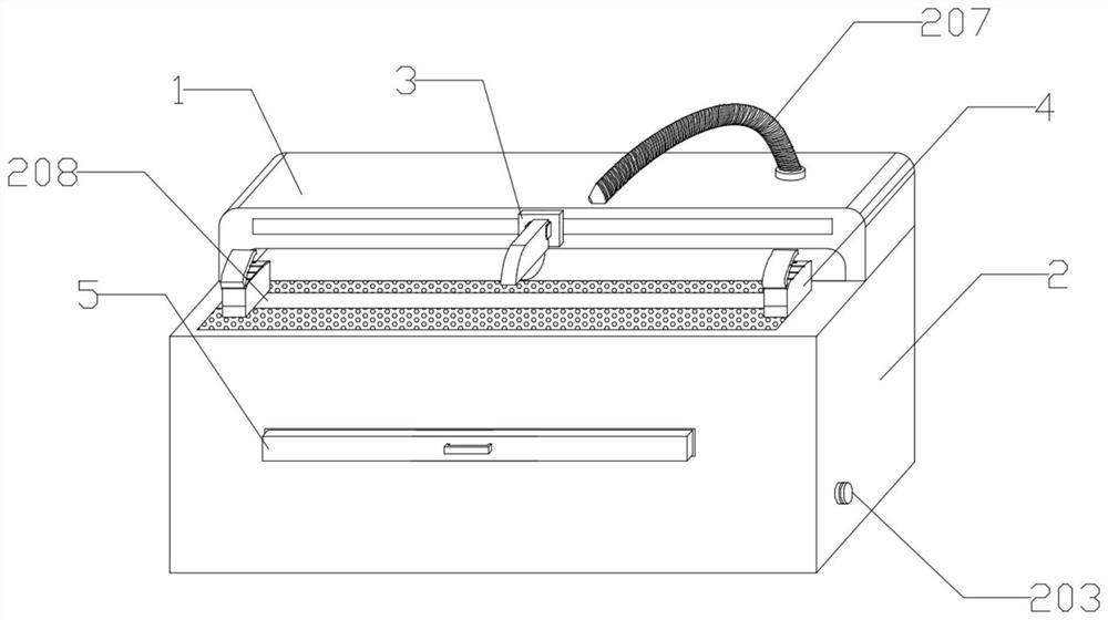
[0033] In order to solve the existing problem of not being able to fix titanium alloys of different lengths, titanium alloys tend to be sideways during cutting, which affects cutting efficiency and easily generates flying dust during cutting. If you stay in this environment for a long time, you will easily get "pneumoconiosis" , endangering the life and health of workers, the present invention provides a high-impact titanium alloy cutting equipment for additive use and its use method. The technical solutions in the present invention will be clearly and completely described below in conjunction with the accompanying drawings in the present invention. Obviously, the described inventions are only part of the inventions of the present invention, not all of them. Based on the inventions in the present invention, all other inventions obtained by persons of ordinary skill in the art without making creative efforts belong to the scope of protection of the present invention.
[0034] see Figure 1-6 , the present invention provides a high-impact titanium alloy cutting equipment for additives, including a base 2 for receiving a top seat 1, an electromagnetic slide rail 101 is arranged inside the top seat 1, and one side of the electromagnetic slide rail 101 is connected with a An electromagnetic slider 102, one end of the electromagnetic slider 102 is connected with a cutting assembly 3 of a high-impact titanium alloy for cutting additives, and the inside of the base 2 is provided with an atomization assembly for absorbing titanium alloy cutting dust, and the upper surface of the base 2 is connected to There are clamping components for fastening in high-impact titanium alloys for additives;
[0035] The atomization assembly includes a water storage tank 201 arranged inside the base 2 , the top of the water storage tank 201 is provided with a liquid guiding groove 202 , and the top of the liquid guiding groove 202 is connected with a mesh plate for transporting liquid water, and the mesh plate is arranged on the top of the base 2 surface.
[0036] Further, both sides of the inner wall of the water storage tank 201 are provided with a chute plate 508, the inside of the chute plate 508 is slidably connected with a frame plate 501, the inside of the frame plate 501 is connected with a filter frame 505, and the inside of the filter frame 505 is connected with a filter screen 507 The bottom end of the water storage tank 201 is provided with an outlet pipe 204, and one side of the outlet pipe 204 is connected with a sealing plug 203. The provided sealing plug 203 prevents liquid water from overflowing from the inside of the water storage tank 201.
[0037] Further, both sides of the frame plate 501 are connected with outer clamping plates 502, and both sides of the inner wall of the frame plate 501 are connected with inner clamping plates 503, the cross-sectional shapes of the outer clamping plate 502 and the inner clamping plate 503 are both “L” shapes, and the The "L" shaped outer clamping plate 502 and inner clamping plate 503 facilitate the connection between the frame plate 501 and the chute plate 508, and the filter frame 505 and the frame plate 501.
[0038] Further, both sides of the filter frame 505 are connected with a fitting plate 506, the cross-sectional shape of the fitting plate 506 is “L”, and the fitting plate 506 and the inner clamping plate 503 cooperate with each other, and the “L” shaped fitting plate 506 provided, the filter frame 505 and the inner clamping plate 503 can cooperate and slide.
[0039] Further, one side of the frame plate 501 is connected with a baffle plate 5, and the two ends of the baffle plate 5 are connected with a sealing plate 504. By setting the sealing plate 504, the sealing performance of the connection between the baffle plate 5 and the base 2 is increased to prevent storage The liquid water inside the water tank 201 overflows.
[0040] Further, one side of the water storage tank 201 is connected with a conduit 206, and one side of the conduit 206 is provided with a pressure pump 205, and the output end of the pressure pump 205 is connected with an atomizing tube 207 for leading out liquid water, and the atomizing tube 207 is arranged on the top seat 1, through the provided atomizing tube 207, the liquid water inside the water storage tank 201 is atomized and pumped out.
[0041] The further clamping assembly includes fixing plates 4 arranged on both sides of the upper surface of the base 2, one side of the fixing plate 4 is fixed on the upper surface of the base 2, and the bottom end of the other side of the fixing plate 4 is connected with an engaging rod 406, and the engaging rod 406 The lower surface of the sleeve 410 is connected with a sleeve 410, and the inside of the sleeve 410 is slidably connected with a limit rod 411. The limit rod 411 is arranged inside the limit groove 208, and the limit groove 208 is opened on the upper surface of the base 2 for connecting the rod. The linear movement of 406 clamps and fixes the titanium alloy through the set fixing plate 4 .
[0042] Further, one side of the upper surface of the fixed plate 4 is provided with a rotating shaft 401, one side of the rotating shaft 401 is connected with a cover plate 402, the lower surface of the cover plate 402 is connected with the upper surface of the fixed plate 4 with a rubber pad 403, and one part of the rubber pad 403 There are multiple sets of grooves 404 for placing the titanium alloy on the side, and the rubber pad 403 is provided to increase the friction between the cover plate 402, the fixing plate 4 and the titanium alloy.
[0043] Further, one side of the lower surface of the cover plate 402 is connected with an engaging rod 405, and one end of the engaging rod 405 is provided with an engaging tooth 407, and the inside of the fixed plate 4 is provided with a locking groove 408, and one side of the inner wall of the locking groove 408 is connected with a There are multiple sets of internal buckle teeth 409 , and the multiple sets of internal buckle teeth 409 are provided to engage and fix the engaging teeth 407 at the bottom of the engaging rod 405 .
[0044] A method for using a high-impact titanium alloy cutting device for adding materials, comprising the following steps:
[0045] Step (A), place one end of the high-impact titanium alloy for additives to be cut in the groove 404 on the upper surface of the fixing plate 4, and first fix the side of the high-impact titanium alloy for additives to facilitate subsequent positioning ;
[0046] Step (B), cover the cover plate 402, drive the engaging tooth 407 at the bottom end of the engaging rod 405, and insert it into the card slot 408, the engaging tooth 407 and the inner buckle tooth 409 are connected to each other to hinder, and the cover plate 402 is engaged Above the fixed plate 4, the titanium alloy is clamped inside the groove 404 of the rubber pad 403, through the rubber pad 403, the frictional force between the high-impact titanium alloy for additives, the cover plate 402, and the fixed plate 4 is increased , to ensure a fixed effect;
[0047] Step (C), move the fixing plate 4 on the other side, drive the sleeve 410 at the bottom end of the connecting rod 406 to slide outside the limit rod 411 inside the limit groove 208 to the other end of the titanium alloy, repeat step (B), and complete the titanium alloy To fix the position, move the fixed plate 4 on the other side, and flexibly adjust the distance between the fixed plates 4 to ensure the clamping effect;
[0048] Step (D), controlling the movement of the electromagnetic slider 102 on one side of the electromagnetic slide rail 101, so that the cutting assembly 3 cuts the titanium alloy, controlling the electromagnetic slider 102 to drive the cutting assembly 3 to move, and adjusting the cutting position of the titanium alloy;
[0049] Step (E), control the operation of the pressure pump 205, pump the liquid water inside the water storage tank 201 through the outlet pipe 204 into the atomizing pipe 207 and spray it to the surface of the titanium alloy, absorb the dust generated during the cutting of the titanium alloy, and pass through the base 2 The mesh of the surface stencil is guided to the surface of the filter 507 below the liquid guide tank 202 for filtration, the liquid water is separated from the dust, and collected into the water storage tank 201 to complete the collection of liquid water, re-collect the used liquid water, and reduce the liquid water. waste of resources;
[0050] Step (F), after use, open the baffle plate 5, drive the frame plate 501 to slide out from the chute plate 508, take out the filter screen 507 inside it from the filter frame 505, and replace the filter screen 507 , and then snap the fitting plates 506 on both sides of the filter frame 505 into the inner clamping plate 503, complete the reset of the baffle plate 5, replace or clean the filter screen 507, ensure the dust filtering effect, and prevent the dust from clogging the atomizing tube 207 .
[0051] A high-impact-resistant titanium alloy cutting equipment for material addition and its use method of the present invention have the following advantages:
[0052] 1. The present invention controls the direction of the atomization tube during the titanium alloy cutting process by setting the atomization component, activates the pressure pump, sprays the liquid water inside the water storage tank through the atomization tube to thin the surface of the titanium alloy, and reduces the amount of titanium alloy. The dust generated during cutting makes the liquid water mixed with dust and transported to the surface of the filter screen, the dust is separated from the liquid water, and the liquid water is collected into the water storage tank to complete the secondary utilization of liquid water and reduce the waste of water resources. After the end, the filter screen is taken out from the water storage tank by pulling the baffle, and the filter screen is cleaned or replaced to ensure the dust filtering effect of the filter screen.
[0053] 2. The present invention clamps and fixes the high-impact-resistant titanium alloy for the additive material with cutting between the fixed plates and the cover plates on both sides through the clamping assembly provided, so that it is clamped and fixed by the rubber pad between the two , the rubber pad is made of rubber material, which can increase the friction between the titanium alloy, the fixing plate and the cover plate, improve the fixing effect of the titanium alloy, prevent it from sideways during cutting, and improve the cutting effect. The plate adjusts the distance between the two fixed plates to match titanium alloys of different lengths, which improves the clamping flexibility of the fixed plate to the titanium alloy and improves the use effect.
[0054] Although the invention of the present invention has been shown and described, it will be understood by those skilled in the art that various changes, modifications, substitutions and variations can be made to these inventions without departing from the principle and spirit of the present invention. , the scope of the invention is defined by the appended claims and their equivalents.

PUM

no PUM

Description & Claims & Application Information

We can also present the details of the Description, Claims and Application information to help users get a comprehensive understanding of the technical details of the patent, such as background art, summary of invention, brief description of drawings, description of embodiments, and other original content. On the other hand, users can also determine the specific scope of protection of the technology through the list of claims; as well as understand the changes in the life cycle of the technology with the presentation of the patent timeline. Login to view more.

Similar technology patents

Device and method for detecting substrate

InactiveCN104568973Areduce waste
Owner:BOE TECH GRP CO LTD +1

Air blocking panel assembly for a server or it rack

InactiveUS20160205812A1reduce waste
Owner:TATE ACCESS FLOORS LEASING

Automatic disposal and packaging device for kitchen garbage

ActiveCN110577040Areduce wastesave resources
Owner:PUJIANG COUNTY LIDING ENVIRONMENT PROTECTION EQUIP CO LTD

Classification and recommendation of technical efficacy words

  • reduce waste

Lighting system and method of deflection

InactiveUS20130051008A1reduce wasteconserve unnecessary waste
Owner:SHEW LARRY N

Disposable paint cup

InactiveUS20050258271A1reduce waste
Owner:ILLINOIS TOOL WORKS INC

Communication method between base station and user terminal and corresponding devices

InactiveCN102045865Areduce wasteImprove frequency utilization
Owner:HUAWEI TECH CO LTD
Why Eureka
Try Eureka