Check patentability & draft patents in minutes with Patsnap Eureka AI!

Reflection-type afocal optical system

An afocal optical system and reflective technology, applied in the optical field, can solve the problems of large volume, large beam incident angle, and high difficulty of plane mirror image stabilization components, and achieve the effect of reducing light loss and reducing the size of the central hole

Pending Publication Date: 2022-06-24
成都浩孚科技有限公司
View PDF1 Cites 0 Cited by
  • Summary
  • Abstract
  • Description
  • Claims
  • Application Information

AI Technical Summary

Problems solved by technology

If this design is used for airborne sighting, it shows two shortcomings. First, it is difficult to use a plane mirror as an image stabilization element, because the incident angle of the beam is large, and it is only suitable for image stabilization in one direction; Second, the primary image is far to the right of the primary mirror, making the system relatively large

Method used


Image

  • Reflection-type afocal optical system
  • Reflection-type afocal optical system
  • Reflection-type afocal optical system

Examples


Embodiment 1

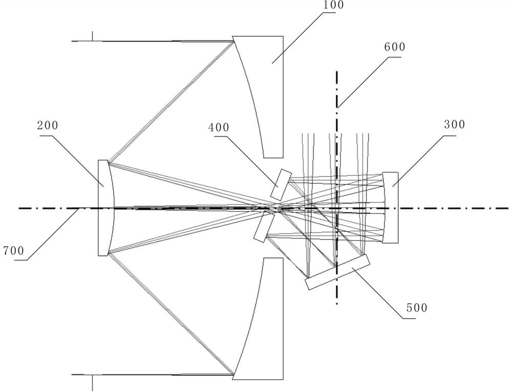
[0029] like figure 1 As shown, a reflective afocal optical system includes a primary mirror 100, a secondary mirror 200, a third mirror 300, a plane mirror A400 and a plane mirror B500, wherein the optical power of the primary mirror 100, the secondary mirror 200 and the third mirror 300 is not Zero and arranged with the optical axis, forming a common optical axis A700;

[0030] There is a through hole in the middle of the primary mirror;

[0031] The secondary mirror 200 is located on the reflection side of the primary mirror 100, receives the light beam reflected by the primary mirror 100, collects the light beam reflected by the primary mirror 100, and reflects it from the through hole;

[0032] The three mirrors are located on the reflection side of the secondary mirror and behind the primary mirror, and receive the light beam reflected by the secondary mirror;

[0033] The plane mirror A400 receives the light beam reflected by the three mirrors, and is located between t...

Embodiment 2

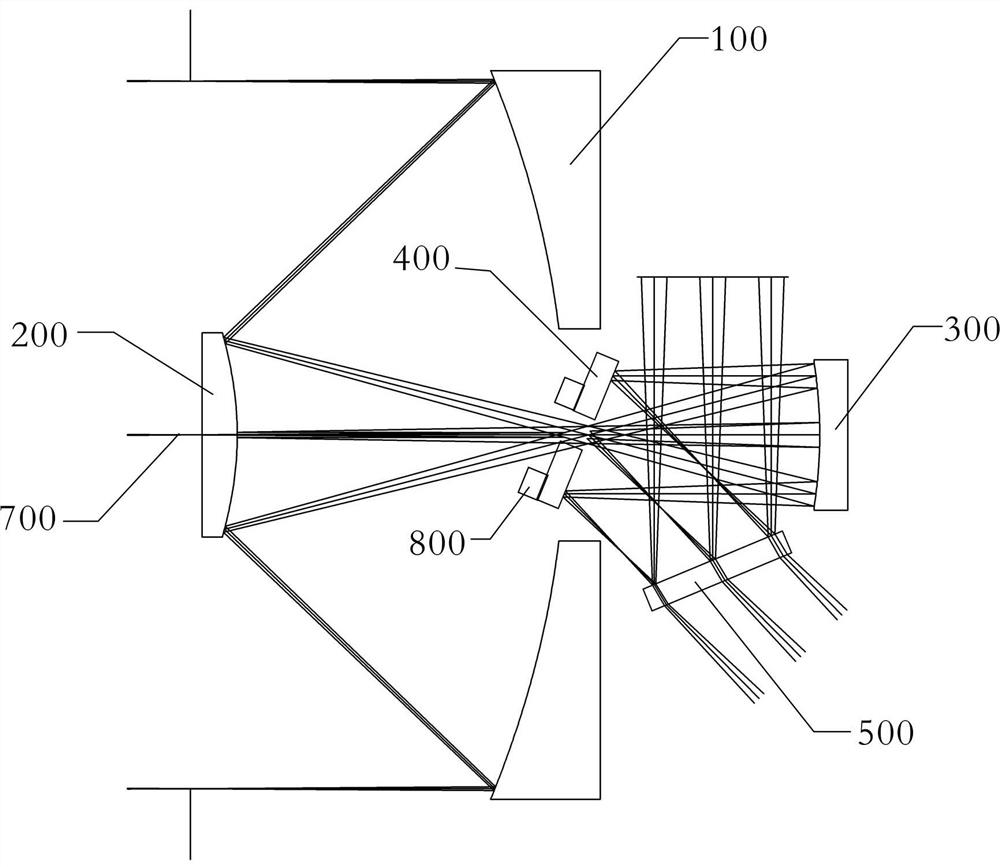
[0045] like figure 2 As shown, a reflective afocal optical system includes a primary mirror 100, a secondary mirror 200, a third mirror 300, a plane mirror A400 and a plane mirror B500, wherein the optical power of the primary mirror 100, the secondary mirror 200 and the third mirror 300 is not Zero and arranged with the optical axis, forming a common optical axis A700;

[0046] There is a through hole in the middle of the primary mirror;

[0047] The secondary mirror 200 is located on the reflection side of the primary mirror 100, receives the light beam reflected by the primary mirror 100, collects the light beam reflected by the primary mirror 100, and reflects it from the through hole;

[0048] The three mirrors are located on the reflection side of the secondary mirror and behind the primary mirror, and receive the light beam reflected by the secondary mirror;

[0049] The plane mirror A400 receives the light beam reflected by the three mirrors, and is located between th...


PUM


Abstract

The invention discloses a reflective afocal optical system which comprises a primary mirror, a secondary mirror, a third mirror, a plane mirror A and a plane mirror B. The focal power of the primary mirror, the focal power of the secondary mirror and the focal power of the third mirror are not zero, and the primary mirror, the secondary mirror and the third mirror are arranged on the same optical axis to form a common optical axis A; a through hole is formed in the middle of the primary mirror; the secondary mirror receives the light beam reflected by the primary mirror, reflects the light reflected by the primary mirror again and emits the light from the primary mirror through hole; the third mirror receives the light beam reflected by the secondary mirror; the plane mirror A receives the light beam reflected by the third mirror and reflects and steers the light beam, and a middle through hole A through which the light beam reflected by the secondary mirror passes is formed in the middle of the plane mirror A; the plane mirror B receives the light beam reflected by the plane mirror A and reflects and steers the light beam to form an optical axis B after steering, and the optical axis B is perpendicular to the optical axis A; according to the invention, the volume of the whole system is compressed, and image stabilizing elements can be arranged more easily.

Description

technical field [0001] The invention relates to the field of optics, in particular to a reflective afocal optical system. Background technique [0002] In order to obtain more information, distinguish more details, and collect more energy, modern photoelectric sighting equipment continues to expand in the direction of multi-band, long focal length, and large aperture. On this basis, improving multi-spectral integration and product stability accuracy is also an important development trend. In principle, the more optical paths shared by multiple spectral segments, the higher the integration and coaxial stability. For airborne photoelectric sighting equipment, in addition to the above characteristics, the size and weight of the system are as important as performance indicators. For long focal length systems, optical axis control measures are also required to solve the problems caused by platform movement or vibration. image instability problem. [0003] The reflective design...

Claims


Application Information

Patent Timeline
Patent Type & Authority Applications(China)
IPC IPC(8): G02B17/06G02B26/08G02B27/00
CPCG02B17/0694G02B17/0647G02B17/0652G02B26/0816G02B27/0025
Inventor 曾钦勇杨雄尹小杰
Owner 成都浩孚科技有限公司
Features
  • R&D
  • Intellectual Property
  • Life Sciences
  • Materials
  • Tech Scout
  • Unparalleled Data Quality
  • Higher Quality Content
  • 60% Fewer Hallucinations
Learn More