Pressing plate buckling structure and power supply connector using pressing plate buckling structure

A technology of power connectors and pressure plates, which is applied in the direction of connection and connection device components, circuits, etc., can solve the problems of easy breakage, claw breakage, deformation, etc., and achieve the effect of avoiding cracking and deformation

Pending Publication Date: 2022-06-24
中航光电(广东)有限公司
View PDF0 Cites 0 Cited by
  • Summary
  • Abstract
  • Description
  • Claims
  • Application Information

AI Technical Summary

Problems solved by technology

[0003] The disadvantages of the elastic claw structure are: ①The deformation of the claw is large when it is loaded, and it is prone to breakage. When the parts manufacturer produces it, if the molding parameters are improper, the claw will be brittle (that is, the bending angle cannot reach the design, and the spring will Claw roots are broken), and the risk of elastic structure dimension out of tolerance is high, which is not conducive to production
②Improper operation on the production site, there is a risk of breaking the claws
In addition, when the claws are loaded, the hand feeling is poor, the assembly efficiency is low, and there is no obvious indication of the position. After the assembly is completed, it is necessary to 100% check whether all the claws are in the groove, check whether the claws are broken, and the production efficiency is low.
③The holding force of the elastic claw structure is limited
[0004] The disadvantages of the piercing buckle structure are: the piercing buckle structure is forced to squeeze in by the side wall of the insulator; when the height of the buckle is too high, it is easy to cause assembly difficulties, and there is a risk of breaking and deforming the side wall of the insulator due to excessive force ;When the buckle height is too low, combined with the gap between the insulator and the pressure plate, the tolerance of each feature, and the interference of the buckle is too low, the pressure plate has insufficient holding force and comes out many times, and quality problems are extremely prone to occur

Method used


Image

  • Pressing plate buckling structure and power supply connector using pressing plate buckling structure
  • Pressing plate buckling structure and power supply connector using pressing plate buckling structure
  • Pressing plate buckling structure and power supply connector using pressing plate buckling structure

Examples


Embodiment Construction

[0023] The technical solutions of the present invention will be further described below with reference to the accompanying drawings and preferred embodiments.

[0024] An embodiment of a pressure plate snap-fit ​​structure of a power connector:

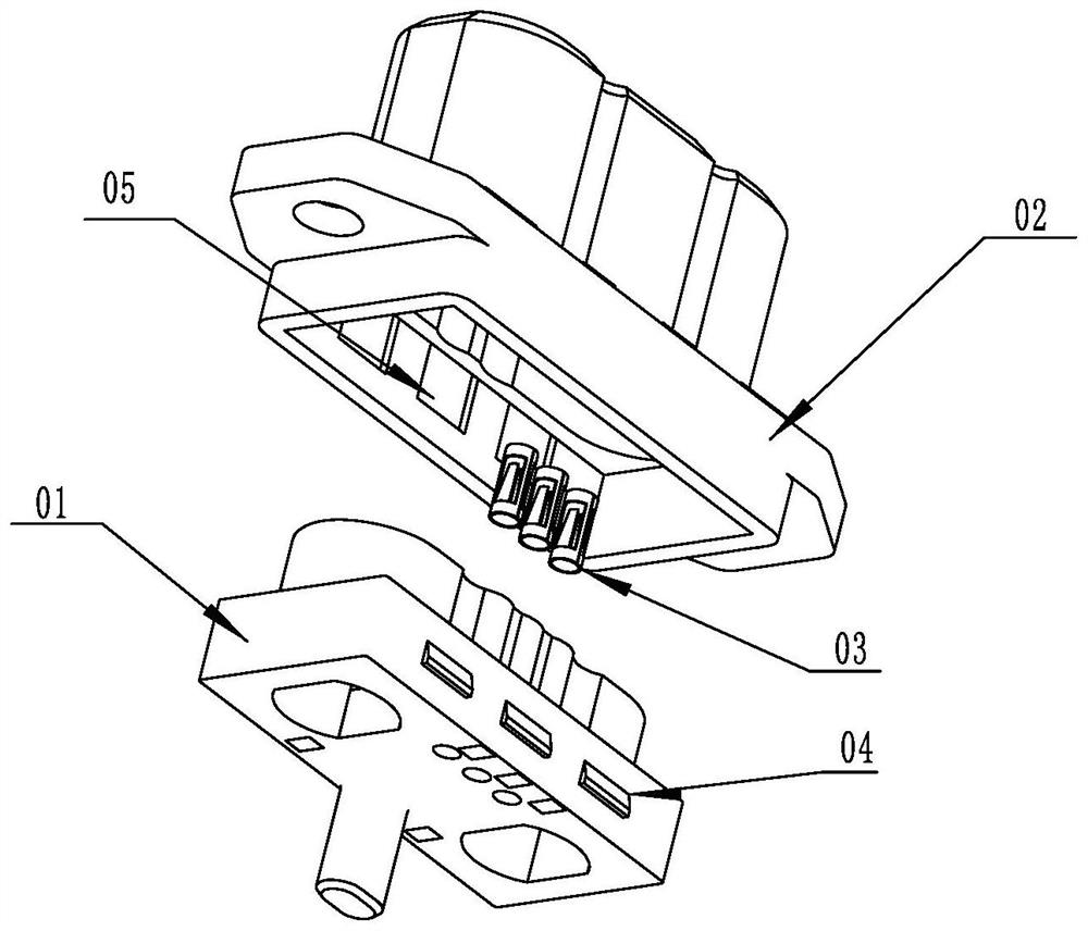
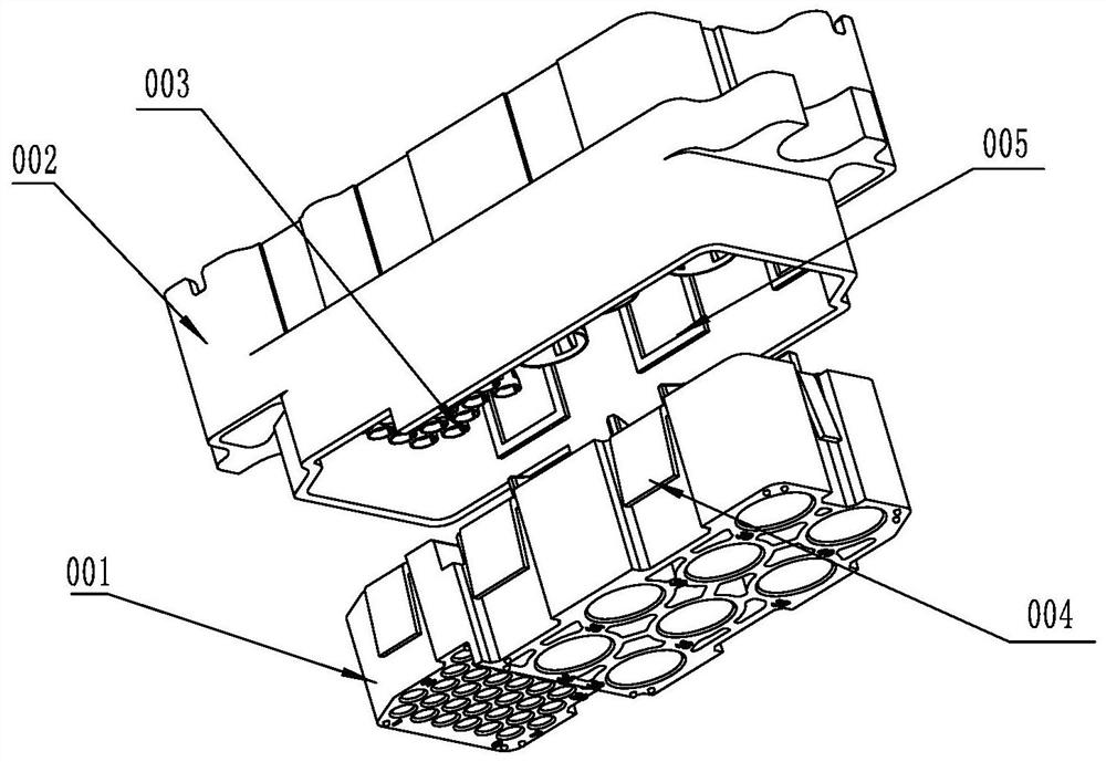
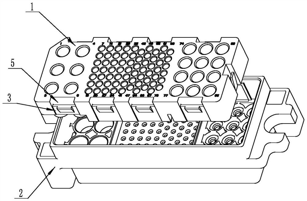
[0025] like Figure 3 to Figure 7 , the pressure plate buckle structure includes a pressure plate 1 and an insulator 2 that are buckled with each other, the side of the pressure plate 1 is provided with a buckle 3, the inner wall of the insulator 2 is provided with a buckle slot 4, and the pressure plate 1 is provided on the buckle 3. The deformation groove 5 on the inner side makes the buckle form a cantilever beam 31 with both ends fixed on the pressure plate. 5 is used for the buckle 3 to deform toward the inside of the deformation groove when the buckle 3 is subjected to the buckling force fed back by the insulator. Therefore, when the pressure plate 1 is forcibly installed into the insulator 2, the outer wall of the insulator a...


PUM


Abstract

The invention relates to a pressing plate buckling structure and a power connector using the pressing plate buckling structure, the pressing plate buckling structure comprises a pressing plate (1) and an insulator (2), the side portion of the pressing plate (1) is provided with a buckle (3), the inner wall of the insulator (2) is provided with a clamping groove (4), and the pressing plate (1) is provided with a deformation groove (5) located on the inner side of the buckle (3) so that the buckle can form a cantilever beam (31) with the two ends fixed to the pressing plate. A protrusion (32) matched with the clamping groove (4) in a stopping mode is arranged on the outer side of the buckle, and the deformation groove (5) is used for enabling the buckle (3) to deform towards the interior of the deformation groove when the buckle (3) is subjected to buckling force fed back by the insulator. According to the pressing plate buckling structure, the requirement for the retaining force between the buckle and the insulator is met, the deformation amount of a single-side structure is not too large in the assembling process, and therefore the risks of cracking, deformation and the like are avoided.

Description

technical field [0001] The invention belongs to the technical field of connectors, and particularly relates to a pressure plate buckle structure and a power connector using the pressure plate buckle structure. Background technique [0002] For power connectors in the communication field, factory-made wire connectors often use a positioning spring structure. When in use, the contact piece is inserted into the connector after crimping the cable, and the contact piece is fixed by the positioning spring. The pressure plate and the insulator play the role of a fixed contact and a positioning spring, and a strong holding force is required between the pressure plate and the insulator. At present, there are two commonly used pressure plate buckle structures, one is the puncture type buckle structure, such as figure 1 , including the pressure plate 01, the insulator 02 and the positioning spring 03 installed between the two, the pressure plate 01 has a buckle 04, when the pressure ...

Claims


Application Information

Patent Timeline
Patent Type & Authority Applications(China)
IPC IPC(8): H01R13/40H01R13/533
CPCH01R13/40H01R13/533
Inventor 赵若曦李文采曹李菠
Owner 中航光电(广东)有限公司
Why Eureka
Try Eureka