
Spraying rotary clamp for spraying and winding thermal insulation pipe and clamping method

A technology of rotating fixtures and heat preservation pipes, applied in the direction of spraying devices, etc., can solve the problems of eccentricity and asynchronous expansion between the steel pipe to be sprayed and the rotating trolley, and achieve the goals of reducing socket fitting time, improving efficiency, and improving spraying quality Effect

Pending Publication Date: 2022-06-28
SHANDONG DONGHONG PIPE IND
View PDF7 Cites 0 Cited by
  • Summary
  • Abstract
  • Description
  • Claims
  • Application Information

AI Technical Summary

Problems solved by technology

[0005] The purpose of the present invention is to provide a spraying and winding thermal insulation pipe spraying rotary fixture and clamping method to solve the problem of eccentricity between the steel pipe to be sprayed and the rotating shaft of the rotary trolley caused by the asynchronous expansion of the expansion fixture of the existing oil cylinder (or air cylinder)

Method used


Image

  • Spraying rotary clamp for spraying and winding thermal insulation pipe and clamping method

Examples


Embodiment 1

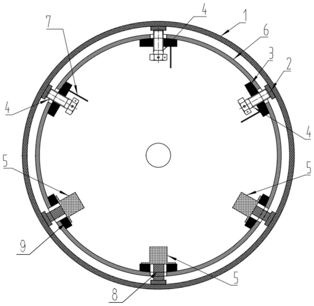
[0028] like figure 1 As shown, the present embodiment provides a spraying rotating fixture for spraying, winding and insulating pipes, including a socket sleeve 6 with an outer diameter smaller than the steel pipe 1 to be sprayed, one end of which is used to connect with the rotating shaft of the rotating trolley, and the other end is along the circumference of the The direction is provided with at least two continuously arranged positioning rods 4 and at least two continuously arranged jacking rods 8, and the axial directions of the positioning rods 4 and the jacking rods 8 are pushed along the radial direction of the socket sleeve 6;

[0029] Wherein, the arc chord length formed by any two positioning rods 4 along the circumference is smaller than the diameter of the circumference, and the arc formed by pushing the top of the positioning rod 4 is overlapped with the inner wall of the steel pipe 1 to be sprayed for positioning. The rod 8 and the positioning rod 4 jointly supp...

Embodiment 2

[0044] According to the difference between the inner diameter of the steel pipe 1 to be sprayed and the outer diameter of the socket sleeve 6, the height of the push of the positioning rod 4 is determined, usually the height after the positioning rod 4 is pushed (the distance between the top of the positioning rod 4 and the outer wall of the socket sleeve 6 ) is equal to the difference between the inner diameter of the steel pipe 1 to be sprayed and the outer diameter of the socket sleeve 6, or slightly larger, leaving a certain amount of compensation to compensate for the gap between the threads.

[0045] After the pushing of the positioning rod 4 is completed, the arc formed by the connection at the top can be overlapped with the inner wall of the steel pipe 1 to be sprayed. On the cylinder 6, the top of the positioning rod 4 is in contact with the inner wall of the steel pipe 1 to be sprayed, so that the concentric positioning with the socket sleeve 6 can be realized, the pu...


PUM


Abstract

The invention belongs to the technical field of spraying thermal insulation pipe production, and particularly relates to a spraying rotating clamp for spraying and winding a thermal insulation pipe and a clamping method.The spraying rotating clamp comprises a socket sleeve with the outer diameter smaller than that of a to-be-sprayed steel pipe, and one end of the socket sleeve is used for being connected with a rotating shaft of a rotating trolley; at least two continuously-arranged positioning rods and at least two continuously-arranged jacking rods are arranged at the other end of the socket sleeve in the circumferential direction, and the axial directions of the positioning rods and the jacking rods are pushed in the radial direction of the socket sleeve; wherein the chord length of an arc formed by any two positioning rods along the circumference is smaller than the diameter of the circumference, the arc formed by connecting the tops of the positioning rods is pushed to coincide with the inner wall of a to-be-sprayed steel pipe for positioning, and the inner wall of the to-be-sprayed steel pipe is jointly supported by pushing the jacking rods and the positioning rods; through pushing of the positioning rods, an arc formed by connecting the tops of the positioning rods coincides with the inner wall of the to-be-sprayed steel pipe for positioning, and it is ensured that the to-be-sprayed steel pipe and the socket sleeve are concentric.

Description

technical field [0001] The invention belongs to the technical field of the production of spraying thermal insulation pipes, and particularly relates to a spraying rotating fixture and a clamping method for a spraying winding thermal insulation pipe. Background technique [0002] In the production process of spray insulation pipe, the steel pipe needs to be placed on two rotating trolleys when spraying. Use a rotary trolley to rotate the steel pipe while controlling forward or backward to spray polyurethane with a spray gun in the spray area. [0003] In order to realize that the steel pipe to be sprayed is clamped by the rotating trolley, an oil cylinder (or cylinder) expansion clamp is set on its rotating shaft, and the clamp is provided with a plurality of evenly distributed jacking rods along the circumferential direction of the rotating shaft, and each jacking rod corresponds to one Cylinder (or cylinder). After being sleeved into the steel pipe to be sprayed, the radi...

Claims


Application Information

Patent Timeline
Patent Type & Authority Applications(China)
IPC IPC(8): B05B13/02
CPCB05B13/0228
Inventor 倪奉尧张岩徐海金刘伯胜孔伟川
Owner SHANDONG DONGHONG PIPE IND
Learn More