
Rotary ejection mechanism of injection mold

A rotary ejection and injection mold technology, applied in the field of injection molds, can solve the problems of cumbersome and unstable movement process, undercuts sticking to the ejector mechanism, low product yield, etc., to achieve a streamlined and stable movement process and ensure stable demoulding , The effect of improving the yield

Pending Publication Date: 2022-06-28
ZHEJIANG TAIZHOU MEIDUO MOLD CO LTD
View PDF0 Cites 0 Cited by
  • Summary
  • Abstract
  • Description
  • Claims
  • Application Information

AI Technical Summary

Problems solved by technology

The ejection mechanism in the prior art is complex in structure, bulky, and the movement process is cumbersome and unstable; and the undercut is prone to sticking to the ejection mechanism during demoulding, resulting in demoulding failure and low product yield

Method used


Image

  • Rotary ejection mechanism of injection mold
  • Rotary ejection mechanism of injection mold
  • Rotary ejection mechanism of injection mold

Examples


Embodiment Construction

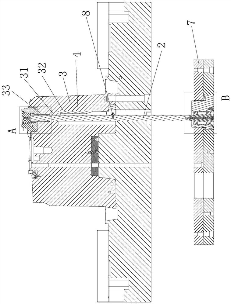
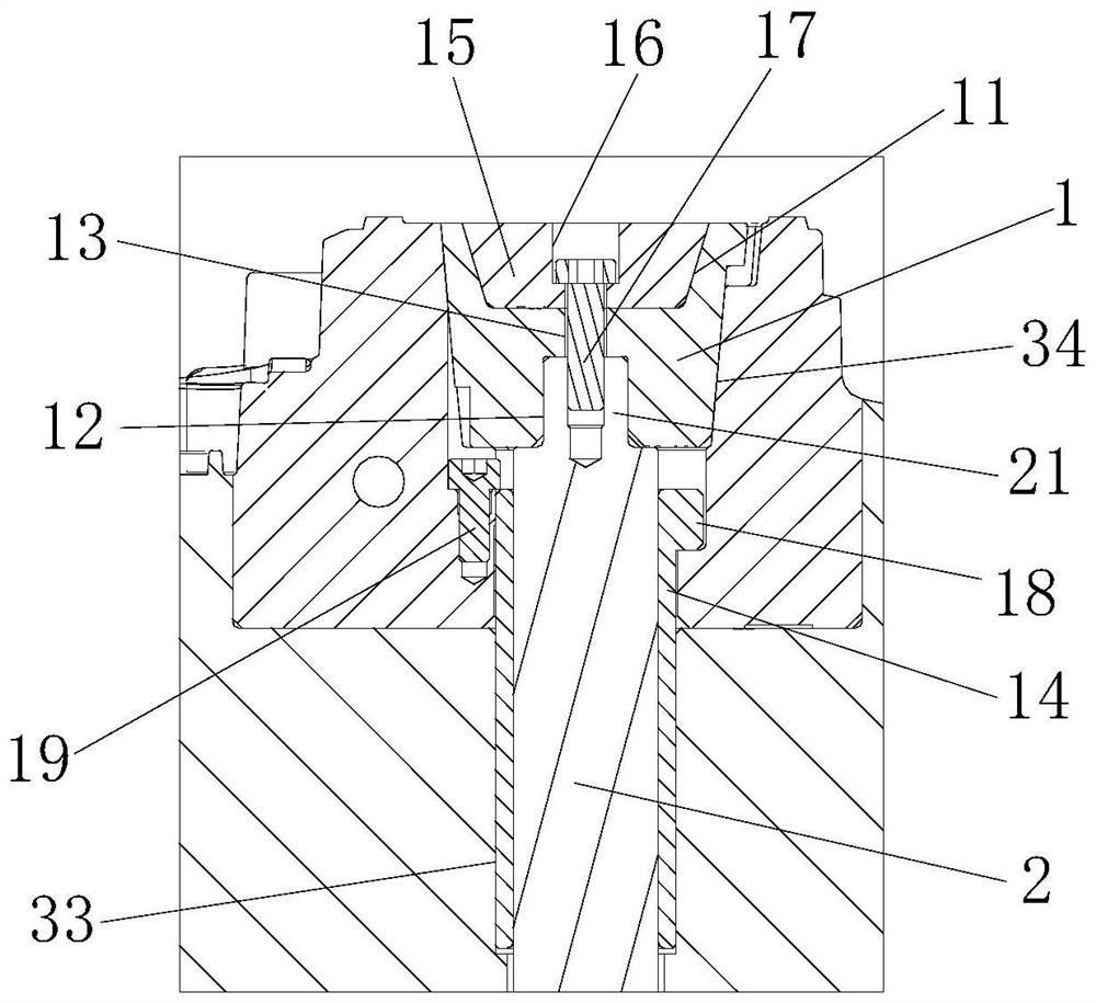
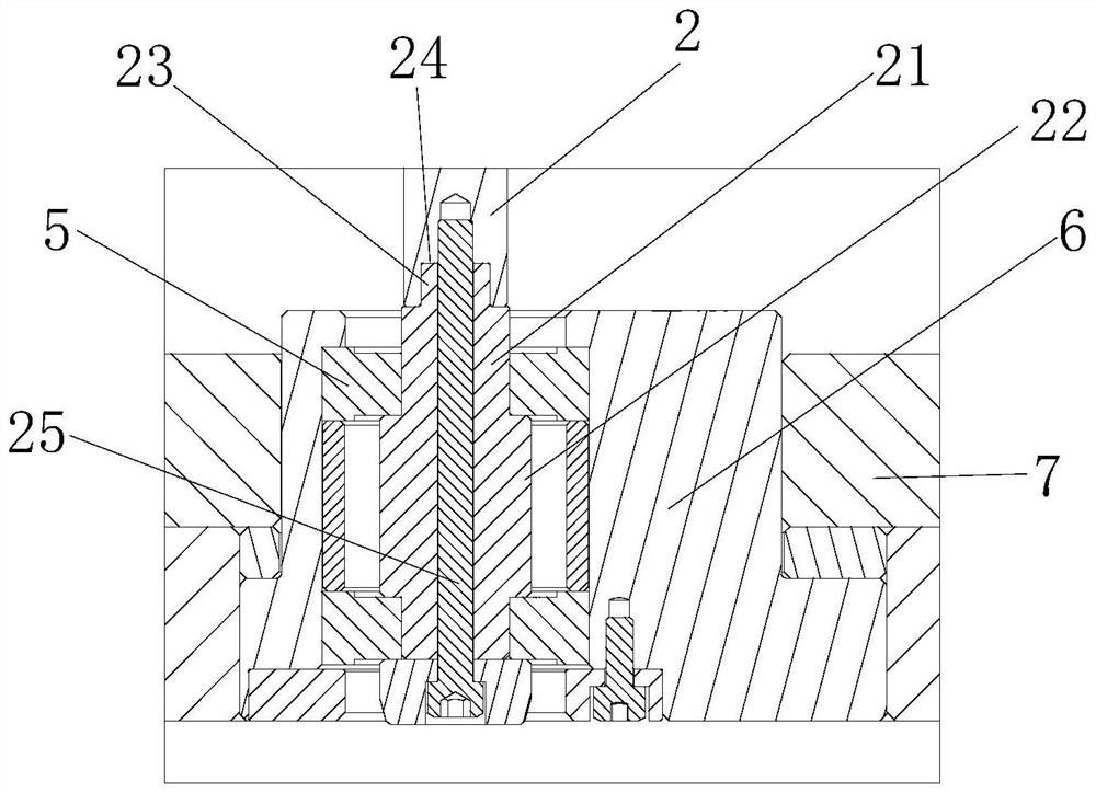
[0021] The present invention will be further described below with reference to the accompanying drawings and specific embodiments. like Figure 1-4 As shown, the rotary ejection mechanism of the injection mold includes a movable mold, and the movable mold includes a movable mold insert 3 , an ejector plate 7 , a rotary core-pulling block and a guide block 4 . The rotary core-pulling block includes a rotary head 1 and a connecting rod 2 that are connected to each other. A rotary core-pulling groove 34 is made in the movable die insert 3. The rotary head 1 is located in the rotary core-pulling groove 34. Snap-molded molding bumps 10 . When the mold is closed, the rotary head 1 and the movable mold insert 3 together form part of the mold cavity. An ejection hole 31 is formed in the movable mold, the rotary core pulling groove 34 communicates with the ejection hole 31 , and the connecting rod 2 is located in the ejection hole 31 . The bottom of the connecting rod 2 is connected...


PUM


Abstract

The invention relates to a rotary ejection mechanism of an injection mold, which comprises a movable mold, the movable mold comprises a movable mold insert, an ejector plate, a rotary core-pulling block and a guide block, the rotary core-pulling block is connected with the ejector plate and can rotate relative to the ejector plate, and the guide block is connected with the movable mold insert. The guide block is arranged on the rotary core-pulling block in a sleeving manner and is fixed with the movable mold, a guide groove is formed in the side surface of the guide block, the guide groove comprises an inclined guide groove, a clamping block is arranged on the rotary core-pulling block, and the end part of the clamping block is positioned in the guide groove and can move up and down along the guide groove. Compared with the prior art, the rotary core pulling block rotates to complete core pulling during ejection, the structure is simple, the movement process is simple and stable, the space occupied by the mechanism is reduced, and the mold cost is reduced; and the product can be prevented from sticking to the movable mold insert and the rotary core-pulling block, so that the demolding stability is ensured, and the yield of the product is improved.

Description

technical field [0001] The invention relates to a rotary ejection mechanism of an injection mold, and belongs to the technical field of injection molds. Background technique [0002] When injection molding, it is often encountered that there is an undercut on the product. Some of the inverted buckles have a special structure, and need to be ejected and core pulled at the same time when demoulding. The ejector mechanism in the prior art has a complex structure, a large volume, and a cumbersome and unstable movement process; and the inverted buckle is prone to stick to the ejector mechanism during demolding, resulting in demolding failure and low product yield. SUMMARY OF THE INVENTION [0003] The purpose of the present invention is to provide a rotary ejection mechanism of an injection mold that realizes the smooth demoulding of product upside-down in view of the shortcomings of the prior art. [0004] The technical scheme that the present invention adopts for realizing ...

Claims


Application Information

Patent Timeline
IPC IPC(8): B29C45/44B29C45/40
CPCB29C45/44B29C45/4005
Inventor 高光华江志仁卢章仁杨炯汪明威罗凯史新星
Owner ZHEJIANG TAIZHOU MEIDUO MOLD CO LTD
Learn More