
Detection system of rod position system

A detection system and rod position platform technology, which is applied in the direction of reducing greenhouse gases, climate sustainability, reactors, etc., can solve the problems of inaccurate rod position information and mismatch of real detection performance of rod position system, so as to achieve accurate detection results, The effect of reducing friction and reducing wear

Pending Publication Date: 2022-06-28
SANMEN NUCLEAR POWER CO LTD +1
View PDF1 Cites 0 Cited by
  • Summary
  • Abstract
  • Description
  • Claims
  • Application Information

AI Technical Summary

Problems solved by technology

However, the detection results output by the detection platform do not match the real detection performance of the rod position system. When the rod position system is officially put into use to detect the rod position, there will be some factors that are difficult to detect by the detection platform. The output bar position information is inaccurate

Method used


Image

  • Detection system of rod position system
  • Detection system of rod position system
  • Detection system of rod position system

Examples


Embodiment Construction

[0038] The following are specific embodiments of the present invention and in conjunction with the accompanying drawings, the technical solutions of the present invention are further described, which are not limitations of the present invention. Those skilled in the art can make any modifications to this embodiment as required after reading this specification. Modifications of creative contributions are protected by patent law as long as they are within the scope of the claims of the present invention.

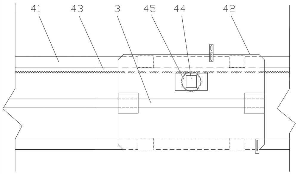
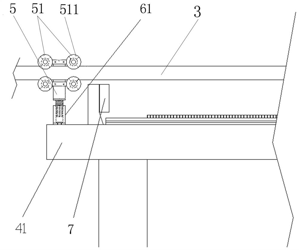
[0039] A detection system of a rod position system, such as figure 1 , including the rod position stage 2 for fixing the rod position detector 1 and the rod position stage 4 for installing the simulated driving rod 3, the external dimensions of the simulated driving rod 3 are the same as those of the real driving rod, and the The material of the simulated drive rod 3 is also the same as that of the real drive rod. like figure 2 and Figure 4 As shown, the pole position tab...


PUM


Abstract

The invention relates to the technical field of nuclear power instrument control, in particular to a detection system of a rod position system, which comprises a rod position table for fixing a rod position detector and a rod position table for mounting a simulation driving rod, the rod position table comprises a support frame and a sliding plate connected to the support frame in a sliding manner, and the simulation driving rod is mounted on the sliding plate. The rack is installed on the supporting frame, the driving device is fixed to the sliding plate, the gear is connected to the driving end of the driving device, and the gear is meshed with the rack. The detection system can simulate the real movement of the driving rod relative to the rod position detector, the rod position system detects the position information of the driving rod, and then the whole process of processing and transmission is carried out. During detection, the gear rotates to drive the movement distance of the simulation driving rod to be compared with rod position information output by the rod position system, so that a more visual, real and comprehensive rod position system detection result compared with the prior art is obtained, and the problems which are difficult to detect in the prior art can be detected easily.

Description

technical field [0001] The invention relates to the technical field of nuclear power instrumentation and control, in particular to a detection system of a rod position system. Background technique [0002] The digital control rod control system and the digital control rod position indication system are both components of the important instrument control system of the nuclear power plant. [0003] Digital control rod control system, referred to as rod control system, its main function is to control the insertion and movement of control rods in the core, so as to realize the start-up, shutdown and power regulation of the reactor. [0004] The digital control rod position indication system, referred to as the rod position system, its main function is to use the rod position detector to detect and obtain the position information of the driving rod connected to the control rod through non-contact electromagnetic induction technology, and the position information of the driving ro...

Claims


Application Information

Patent Timeline
IPC IPC(8): G21C17/00G21C17/10
CPCG21C17/001G21C17/10Y02E30/30
Inventor 金跃明米正宇胡松喻本松郑开源欧卫兵王冠峰王聪张静超郝占峰李江华刘爱青蔡振东
Owner SANMEN NUCLEAR POWER CO LTD
Learn More